1594
Proceedings of the 18
th
International Conference on Soil Mechanics and Geotechnical Engineering, Paris 2013
-160
-120
-80
-40
0
60 80 100 120 140 160 180
Bending moment [kN*m/m]
-160
-120
-80
-40
0
60 80 100 120 140 160 180
-160
-120
-80
-40
0
60 80 100 120 140 160 180
Axial force [kN/m]
-160
-120
-80
-40
0
60 80 100 120 140 160 180
-160
-120
-80
-40
0
60 80 100 120 140 160 180
Start
Start
Start
End
End
End
Start
End
Start
End
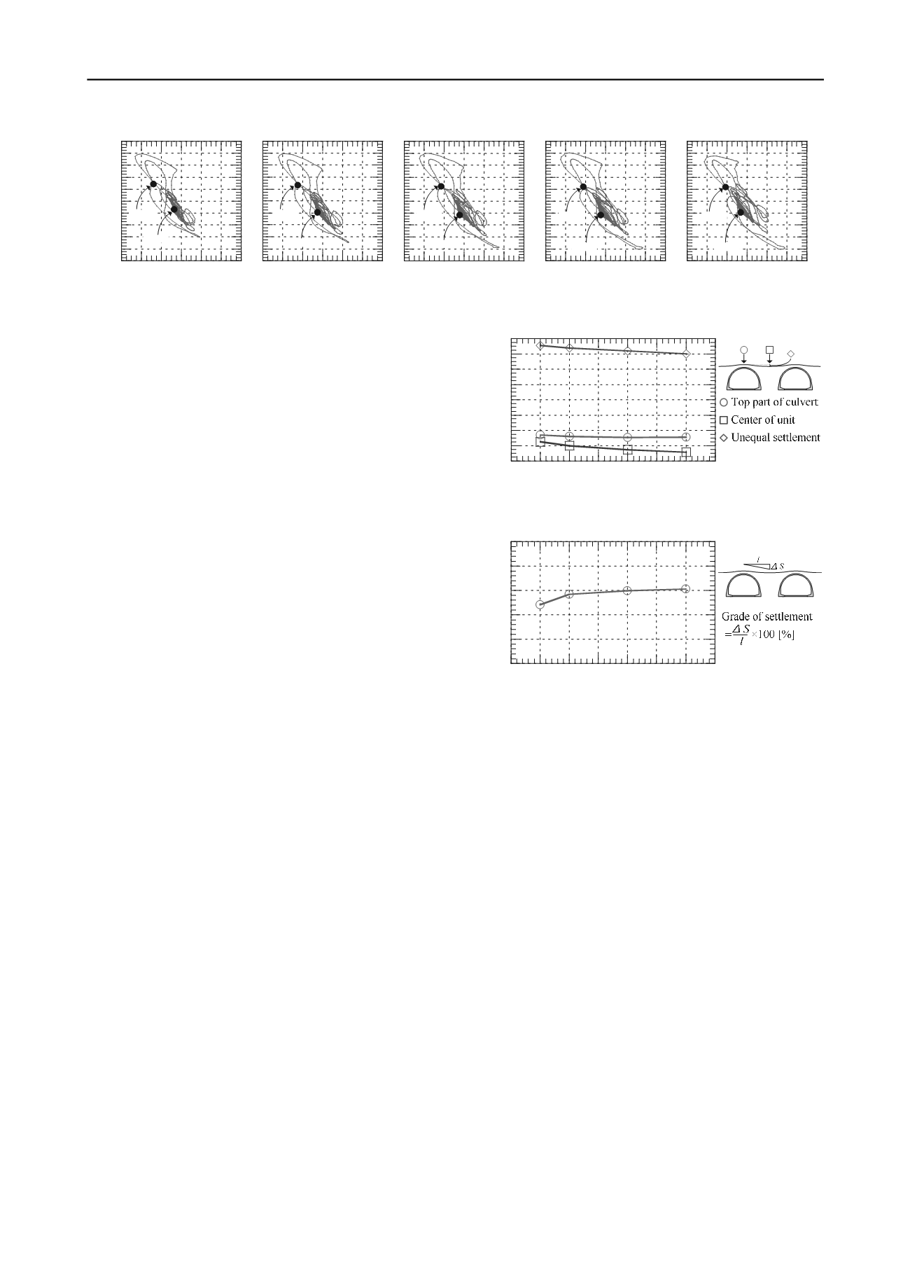
(a) Case-1 (
L
=0.25
H
)
(b) Case-2 (
L
=0.50
H
)
(c) Case-3 (
L
=1.00
H
)
(d) Case-4 (
L
=1.50
H
)
(e) Case-Single
Figure 9. Variation of axial force with bending moment at the right foot.
displacement is large at the boundary between fill and
foundation ground and ground surface. Moreover, when unit
interval is wide, the difference of displacement increases and
comes to the behavior of Case-single.
Figure 8 shows the earth pressure distribution of normal
direction which acts on the boundary portions of the ground and
arch culvert when maximum bending moment is generated at
right foot. When the arch culvert bends to the left, as a result of
seismic force, it turns out that a large earth pressure acts on the
right-hand side of arch culvert. Compared all cases, earth
pressure also becomes large as a unit interval become large.
This could be ascribable to the difference of horizontal
displacement of soil around arch culvert as shown in Figure 7.
On the other hand, near the top part of the arch culvert, a
difference is not seen between cases.
Figure 9 shows the variation of axial force with bending
moment at the right foot. During earthquake, the bending
moment for all cases increase accompanied by increase in axial
force. When all cases are compared, the more unit interval is
wide, the more both axial force and bending moment increase,
and there are few differences between Case-4 and Case-Single.
It can be concluded that arch culverts and surround soil shake
greatly because the volume in the fill part where the rigidity is
comparatively small increases when unit interval is wide.
Figure 10 shows the settlement of ground surface and Figure 11
shows the grade of settlement. The grade of settlement is
defined as unequal settlement
Δ
S
divided by distance from the
top part of arch culvert to the center of the unit
l
. At the top part
of arch culvert, settlement is almost same in all the cases.
However, when the installation interval is wide, the amount of
the subsidence at the center of the unit becomes large. It is
because that the volume in the fill part where the weight is
comparatively large increases when unit interval is wide.
Therefore, Unequal settlement becomes large. But the grade of
settlement is only 0.3% in Case-4 and it does not become a
serious traffic hindrance. Furthermore, surface geometry is
continuity and local discontinuous subsidence like the case of
box culvert does not occur.
4 CONCLUSIONS
In this study, the full-scale numerical analysis has been
executed to clarify the influence of the installation intervals
between consecutive arch culverts on the structures as a whole
and the surrounding soil during earthquake. The following
conclusions can be drawn from the results of this study:
1) When earthquake-proof stability of culvert is examined, the
generation of bending moment at the foot is especially
important, and the influence of the installation interval on
the fill between arch culverts was remarkable at the foot.
2) In case with wide unit interval, large maximum bending
moment is generated compared with the case with narrow
unit interval.
3) For case with wide unit interval, bending moment increases
accompanied by an increase in the axial force. It is thought
that arch culverts shake widely because the volume in the
-16
-14
-12
-10
-8
-6
-4
-2
0
0 0.25 0.5 0.75 1 1.25 1.5 1.75
Settlement [cm]
Unit interval
Case-1 Case-2 Case-3 Case-4
Figure 10. Final ground level displacement and unequal settlement.
0
0.1
0.2
0.3
0.4
0.5
0 0.25 0.5 0.75 1 1.25 1.5 1.75
Grade of settlement [%]
Unit interval
Case-1 Case-2 Case-3 Case-4
Figure 11. Grade of settlement.
fill part where the rigidity is small increases comparatively
when the unit interval is wide.
4) When the installation interval is wide, the amount of the
subsidence at the center of the unit becomes large, hence
unequal settlement becomes large. However, the grade of
settlement is very small and it does not become a serious
traffic hindrance.
5 REFERENCES
Sawamura, Y., Kishida, K. and Kimura, M. 2010. Dynamic centrifuge
model test of Multi-arch culverts embankment. Proc. of the 23rd
KKCNN Symposium on Civil Engineering, Taipei, pp.391-394
Sawamura, Y., Kishida, K. and Kimura, M. 2011. Numerical approach
on dynamic interactive behavior between embankment and installed
multi-arch culverts. Proc. of the 13th Int. Conf. on Computer
Methods and Advances in Geomechanics, Melbourne, pp.798-803
Ye, B., Ye, G. L., Zhang, F. and Yashima, A. 2007. Experiment and
numerical simulation of repeated lipuefaction-consolidation of
sand, Soils and Foundations, Vol.47, No.3, pp.547-558
Nakai, T. and Hinokio, M. 2004. A simple elastoplastic model for
normally and over consolidated soils with unified material
parameters. Soils and Foundations, Vol.44, No.2, pp.53-70
Matsuoka, H. and Nakai, T. 1974. Stress-deformation and strength
characteristics of soil under three different principal stresses,
Proceeding of JSCE, pp.59-70
Zhang, F. and Kimura, M. 2002. Numerical prediction of the dynamic
behaviours of an RC group-pile foundation. Soils and Foundations,
Vol.42, No.3, pp.72-92


