 
          1592
        
        
          Proceedings of the 18
        
        
          th
        
        
          International Conference on Soil Mechanics and Geotechnical Engineering, Paris 2013
        
        
          load alleviation of the foundation ground. This results into the
        
        
          unit interval being smaller than the case where usual fill
        
        
          material is used. Though, the purpose of this study is to examine
        
        
          the difference of the dynamic behavior by unit interval, usual
        
        
          sandy material is used for fill ground. Unit interval L between
        
        
          the precast arches was expressed as a function of the culvert
        
        
          height H. Results of the case with consecutive arch culverts
        
        
          were compared to cases of single arch culvert setting alone. The
        
        
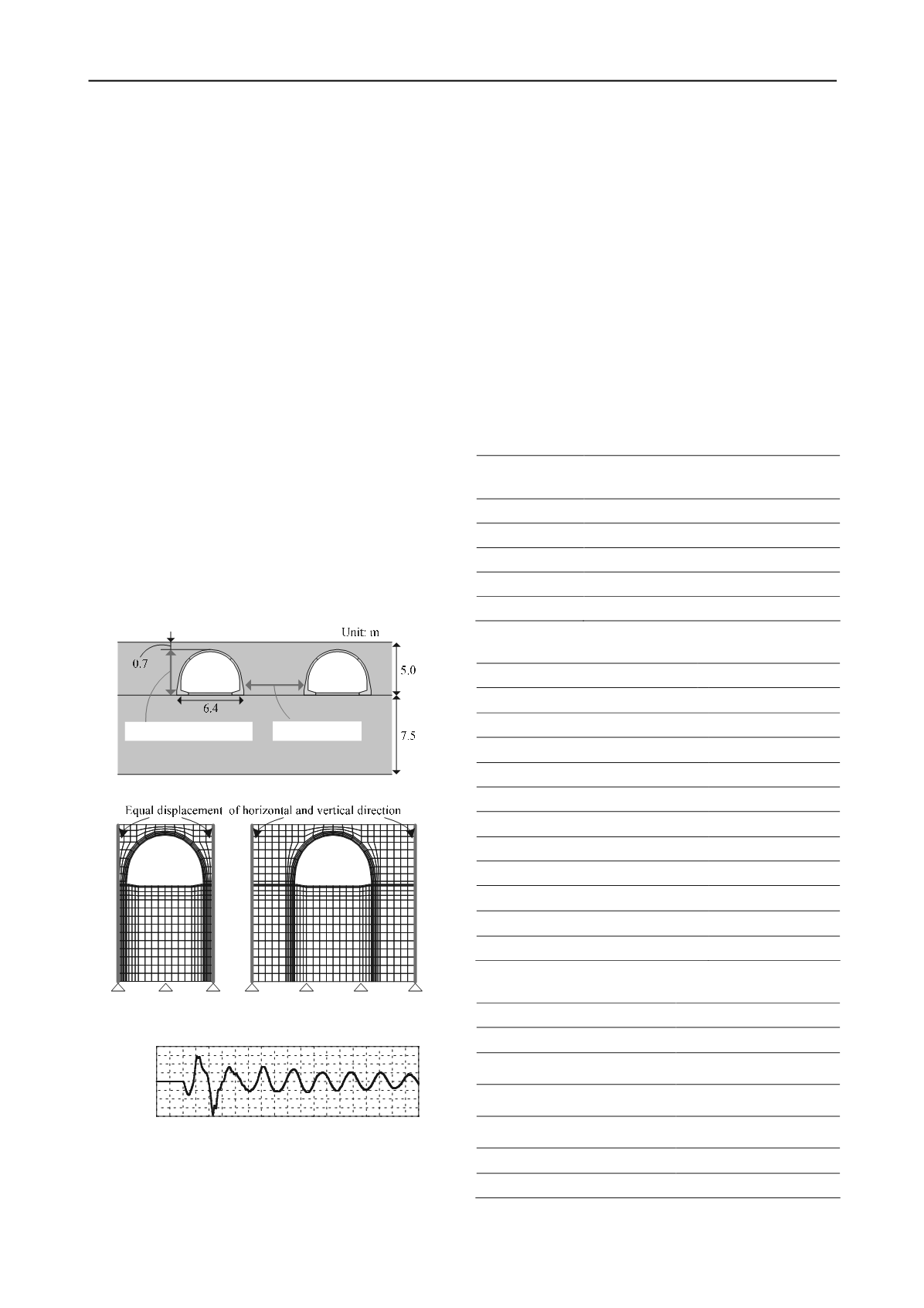
          examination cases are shown in Table 1. In the cases of multi-
        
        
          arch culverts embankment, since several precast arch culverts
        
        
          are set up continuously in the in-situ construction, 1 unit of arch
        
        
          culvert was modeled and both sides of analytical domain were
        
        
          configured equal displacement condition of horizontal and
        
        
          vertical direction. Moreover, the boundary on the bottom area is
        
        
          fixed on all directions. The analysis mesh of Case-1,3 and
        
        
          boundary condition were as shown in Figure 3. On the other
        
        
          hand, in the case of single arch culvert, the width of analytical
        
        
          domain is wide enough (100 m) and boundary condition is same
        
        
          as other cases. The input ground motions used in this study is
        
        
          the time history of acceleration measured in the centrifuge
        
        
          model test when 1 Hz sin wave was inputted by controlling the
        
        
          displacement of vibration table. The input ground motions
        
        
          shown in Figure 4 are applied at the bottom boundary. The time
        
        
          interval of calculation is 0.01 seconds.
        
        
          1.2


            Modeling of ground


          The constitutive model for foundation ground and filling
        
        
          adopted in the present study is subloading


            t


            ij


          model (Nakai and
        
        
          Hinokio, 2004). This model was proposed based on the concept
        
        
          Figure 2. Dimension of multi-arch culverts
        
        
          (a) Case-1 (


            L


          =0.25


            H


          )
        
        
          (b) Case-4 (


            L


          =1.50


            H


          )
        
        
          Figure 3. Analytical mesh and boundary condition
        
        
          -400
        
        
          -300
        
        
          -200
        
        
          -100
        
        
          0
        
        
          100
        
        
          200
        
        
          300
        
        
          400
        
        
          0 1 2 3 4 5 6 7 8 9 10
        
        
          Time [sec]
        
        
          Acceleration [gal]
        
        
          Figure 4. Input wave
        
        
          of SMP (Spatially Mobilized Plane (Matsuoka and Nakai,
        
        
          1974)), in which the influence of the intermediate principal
        
        
          stress can be properly evaluated. Furthermore this model can
        
        
          describe the dependence of the direction of plastic flow on the
        
        
          stress paths, density and confining pressure on the deformation
        
        
          and strength of soils. Same Properties was used for foundation
        
        
          ground and filling as shown in Table 2. The damping coefficient
        
        
          of both ground are assumed as 5%.
        
        
          1.3


            Modeling of arch culvert


          In-situ precast arch culverts are made by joining several precast
        
        
          sections and its joints are connected using pre-stressed concrete
        
        
          wire. The joints stiffness is somewhere between rigid and hinge.
        
        
          However, the arch culvert model in this study was made as an
        
        
          all-in-one design structure. While modeling of structure,
        
        
          nonlinearity of concrete was also considered. For culvert
        
        
          concrete, nonlinear moment-curvature relation was simulated
        
        
          using the AFD model (Zhang and Kimura, 2002), which
        
        
          considered the axial-force dependency according to variable
        
        
          axial force of the structure. The parameter of arch culvert is
        
        
          Table 1. Examination cases
        
        
          Case


            Unit interval


            (Number of node: N, Number of element: E)


          Case-1


            L=0.25H (N:1478 , E:642)


          Case-2


            L=0.50H (N: 1578, E:690)


          Case-3


            L=1.00H (N: 1778, E:786)


          Case-4


            L=1.50H (N: 1978, E:882)


          Case-Single
        
        
          ∞ (N:6278 , E:2946)
        
        
          Table 2. Property of embankment and foundation ground
        
        
          Constitutive model


            Subloading t


            ij


            model


          Unit weight


          (kN/m
        
        
          3
        
        
          )
        
        
          15.76
        
        
          Principal stress ratio at critical sate R
        
        
          cs
        
        
          3.20
        
        
          Poisson’s ratio


          0.30
        
        
          Coefficient of earth pressure at rest K
        
        
          0
        
        
          0.42
        
        
          Void ratio e
        
        
          0
        
        
          0.65


          (stress-dilatancy)


          2.00
        
        
          a (ANN) parameter
        
        
          500
        
        
          OCR
        
        
          1.20
        
        
          Compression index


          0.012
        
        
          Swelling index


          0.0025
        
        
          Damping coefficient h
        
        
          0.05
        
        
          Table 3. Parameter of concrete
        
        
          Constitutive model


            AFD model


          Unit weight


          (kN/m
        
        
          3
        
        
          )
        
        
          19.35
        
        
          Young’s modulus E
        
        
          (kN/m
        
        
          2
        
        
          )
        
        
          2.07
        
        
          ×
        
        
          10
        
        
          7
        
        
          Compressive strength f
        
        
          c
        
        
          (kN/m
        
        
          2
        
        
          )
        
        
          4.92
        
        
          ×
        
        
          10
        
        
          4
        
        
          Tensile strength f
        
        
          t
        
        
          (kN/m
        
        
          2
        
        
          )
        
        
          5.76
        
        
          ×
        
        
          10
        
        
          3
        
        
          Poisson’s ratio


          0.18
        
        
          Damping coefficient h
        
        
          0.02