1602
Proceedings of the 18
th
International Conference on Soil Mechanics and Geotechnical Engineering, Paris 2013
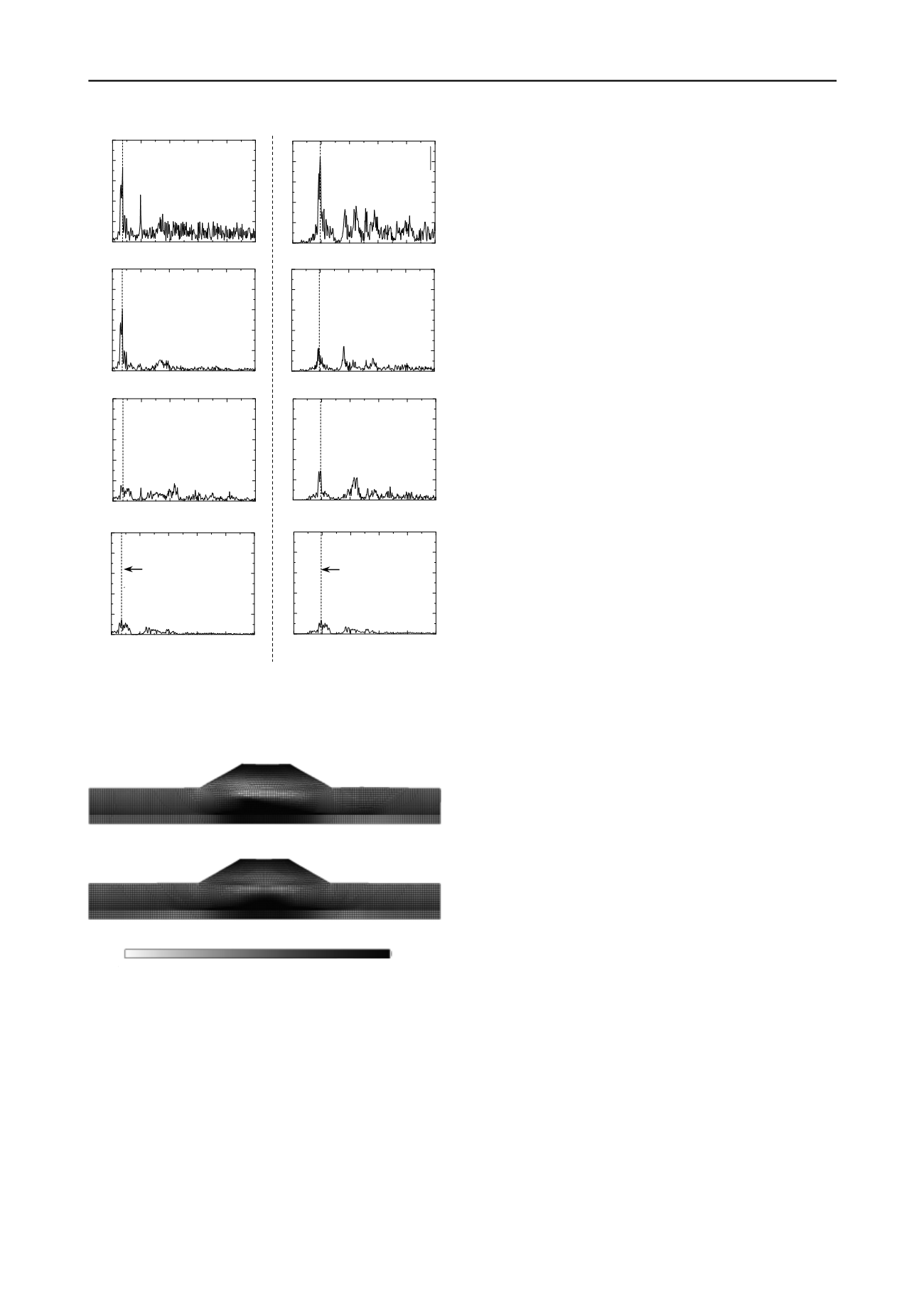
(a) CASE 1 (b) CASE 2
Figure 5. Fourier amplitude spectra of acceleration response
(a) CASE 1
(b) CASE 2
Figure 6. Distribution of excess pore water pressure at the end of the
earthquake
during the earthquake, they underwent hardening accompanied
by plastic volumetric expansion, which resulted in negative
excess pore water pressure. Meanwhile, because the lower
portion of the ground was in a nearly normally consolidated
state of consolidation prior to the earthquake, when subjected to
undrained shear during the earthquake, it underwent hardening
accompanied by plastic compression, which resulted in positive
excess pore water pressure. Although the data are not presented
here due to space limitations, these behaviors can be confirmed
by examining the actual behavior of the soil elements.
Following the earthquake, in the process of returning to the
steady state of pore water pressure, the soil elements in the
upper ground layers, which exhibited negative excess pore
water pressure, absorbed water from the surrounding soil
elements, resulting in softening and, ultimately, the delayed
failure occurred. While this mechanism of delayed failure
applies to both CASE 1 and CASE 2, the substantial difference
in the progression of delayed failure shown in Figure 4 arises
from the difference in the dominant natural frequency mode
between CASE 1 and CASE 2. In CASE 1, because the system
resonated in MODE 1 (upper panel in Figure 2) during the
earthquake, the shear stress first became localized in the ground
and the slip surface progressively expanded from the upper
portion of the ground to the embankment as a result of softening
due to water absorption. Meanwhile, in CASE 2, because the
system resonated in MODE 2 (lower panel in Figure 2) during
the earthquake, the embankment experienced high-amplitude
shaking while the ground did not. For this reason, after the
earthquake, slip failure resulting from softening due to water
absorption occurred first in the embankment. The loss of
equilibrium of force in the embankment induced shear in the
ground components directly under the embankment, which led
to the development of a slip surface in the ground.
6 CONCLUSIONS
In this paper, we proposed a method for calculating the natural
frequency and natural frequency mode in the context of an
initial-boundary value problem for the ground. In addition, we
demonstrated through seismic response analyses of a soil
structure-ground system that seismic motions with different
dominant frequencies result in different dominant natural
frequency modes. We further showed that the progression of
ground deformation, including delayed failure, following an
earthquake is strongly influenced by this natural frequency
mode. In considering initial-boundary value problems of elasto-
plastic materials that are based on finite deformation theory,
although such materials have non-linear geometric and material
properties and their natural frequencies change from moment to
moment, it is still important to understand their natural
frequencies and natural frequency modes, even if only for the
initial state. Finally, although the simulations presented here
used only seismic waves with dominant frequencies close to the
natural frequencies of the system, we have confirmed that the
input of seismic waves of a similar magnitude but with
dominant frequencies far from the natural frequencies does not
result in significant deformation during earthquakes or
subsequent delayed failure.
7 REFERENCES
Noda, T., Asaoka, A. and Nakano, M. 2008a. Soil-water coupled finite
deformation analysis based on a rate-type equation of motion incorporating
the SYS Cam-slay model,
Soils and Foundations
, 45(6), 771-790.
Christian, J. T. 1968. Undrained stress distribution by numerical method,
Proc.
ASCE
, 94, 1331-1345.
Akai, K. and Tamura, T. 1978. Numerical analysis of multi-dimensional
consolidation accompanied with elasto-plastic constitutive equation,
Journal
of JSCE
, 269, 95-104.
Asaoka, A., Noda, T. and Kaneda, K. 1998. Displacement/traction boundary
conditions represented by constraint conditions on velocity field of soil,
Soils
and Foundations
, 38(4), 173-181.
Foss, K, A. 1958. Coordinates which Uncouple the Equations of Motion of
Damped Linear Dynamic Systems,
Journal of Applied Mechanics
, ASME,
32(3), 361-364.
Noda, T. Nakai, K. and Asaoka, A. 2008b. Delayed failure of a clay foundation-
embankment system after the occurrence of an earthquake,
Theoretical and
applied mechanics JAPAN
, 57, 41-47.
Asaoka, A., Noda, T., Yamada, E., Kaneda, K. and Nakano, M. 2002. An elasto-
plastic description of two distinct volume change mechanisms of soils,
Soils
and Foundations
, 42(5), 47-57.
0
2
4
6
8
10
0
10
20
30
40
50
Frequency
f
(Hz)
砕石層上端
0
2
4
6
8
10
0
10
20
30
40
50
Frequency
f
(Hz)
粘土層上端
0
2
4
6
8
10
0
10
20
30
40
50
Frequency
f
(Hz)
天端中央
0
2
4
6
8
10
0
10
20
30
40
50
Frequency
f
(Hz)
入力地震波
MODE-1
0.699(Hz)
<
CASE 1
>
0
2
4
6
8
10
0
10
20
30
40
50
Frequency
f
(Hz)
砕石層上端
0
2
4
6
8
10
0
10
20
30
40
50
Frequency
f
(Hz)
粘土層上端
0
2
4
6
8
10
0
10
20
30
40
50
Frequency
f
(Hz)
MODE-2
1.935(Hz)
入力地震波
0
2
4
6
8
10
0
10
20
30
40
50
Frequency
f
(Hz)
天端中央
<
CASE 2
>
Fourie amplitude spectrum (gal-sec)
Frequency
f
(Hz)
Frequency
f
(Hz)
Embankment crown
Top of clay layer
Top of sand layer
Input wave
Embankment crown
Top of clay layer
Top of sand layer
Input wave
Natural frequency of
MODE 1 : 0.699 Hz
Natural frequency of
MODE 2 : 1.935 Hz
-40
0
20
40
60
u
e
(%)
-20
80


