1593
Technical Committee 203 /
Comité technique 203
-180
-150
-120
-90
-60
-30
0 0 0.25 0.5 0.75 1 1.25 1.5 1.75
Bending moment [kN*m/m]
Unit interval
Case-1 Case-2 Case-3 Case-4
Single
• •
-180
-90
0
90
180
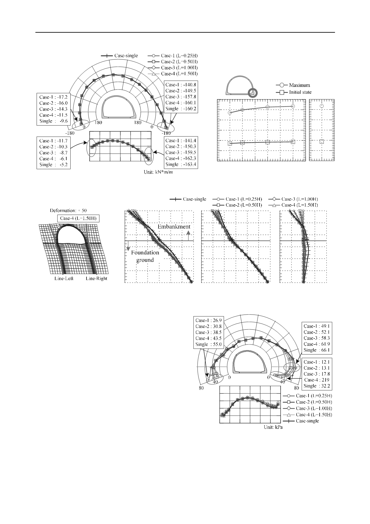
Figure 5. Maximum bending moment occurring at the right foot.
Figure 6. Initial and maximum bending moment at right foot .
-6 -5 -4 -3 -2 -1 0
-12
-10
-8
-6
-4
-2
0
Height from fill ground level [m]
Relative displacement [cm]
-6 -5 -4 -3 -2 -1 0
Relative displacement [cm]
-2 -1 0 1 2
Relative displacement [cm]
(a) Line-Left
(b) Line-Right
(c) Difference of displacement
Figure 7. Horizontal displacement of soil around arch culvert when maximum bending moment is generated at right foot.
shown in Table 3, and the damping coefficient of arch culvert is
assumed as 2%. Moreover, the joint element was arranged on
the boundary division of the culverts and the ground to
represent the influence of friction. The parameters of the joint
were defined from box shear tests between Toyoura sand and
the concrete element.
3 NUMERICAL RESULT
When the stability of concrete structure against earthquake is
evaluated, the point that should be noted most is generation of
excessive bending moment. Figure 5 shows the distribution of
maximum bending moment occurring at right foot, and Figure 6
shows the initial and maximum bending moment at the right
foot. Positive bending moment is defined for the case where
tension is generated inside arc culvert. From these figures, it can
be seen that the influence of the installation interval on the fill
between arch culverts was remarkable in the right foot and the
right end part of invert. The maximum bending moment in
Case-4 increased by about 14 % compared with Case-1.
Moreover, when unit interval is wide, large bending moment is
already generated in the initial state because of the self-weight
of the surrounding soil.
Figure 7 shows the horizontal displacement of soil around arch
culvert when the maximum bending moment is generated at
right foot. In this figure, two lines which is left and right side of
arch culvert are pick up. In Case-1, the difference of
displacement hardly occurs. It is because arch culvert and
0
20
40
60
80
100
Figure 8. Earth pressure distribution of normal direction which acts on
the boundary portions of the ground and arch culvert when maximum
bending moment is generated at right foot.
surrounding soil behave monolithically. On the other
hand, it can be seen that the difference of displacement
has occurred on the left-line and right
-line in other
cases. The difference of
cases. The difference of


