1608
Proceedings of the 18
th
International Conference on Soil Mechanics and Geotechnical Engineering, Paris 2013
the external cover layer (cast-in-place concrete slab), thick
geotextile layers have been used on both sides of PVC
geomembrane. For example, at 28 m high Codole dam in
France, constructed in 1983 and also at 23.5 m high Jibiya dam
in Nigeria, constructed in 1987 (Sembenelli 1990).
Geotextiles are used for filtration purposes as it has the ability
to retain soil particles while alowing free flow of seeping water.
The first application of a geotextile filter in embankment dam
was in 1970 at 17 m high Valcros dam in France (Giroud and
Gross 1993). PET nowwoven geotextile filters were used both
around the down stream gravel drain and also under the rip-rap
protecting the upper portion of the upstream slope (Delmas et
al., 1993).
For new construction, the first dam in which geosynthetics
have been used with reinforcement function was 8 m high
Maraval dam in France, constructed in 1976. The dam has a
sloping upstream face lined with a bituminous geomembrane
and a vertical downstream face obtained by constructing a
multi-layered geotextile-soil mass (Kern 1977). The use of
metallic reinforcement, with more attaractive facing systems in
some of the dams around the world with a low to moderate
height (maximum 22.5 m) as illustrated in ICOLD (1993).
Geosynthetics have also been used to control surficial erosion
(due to rain or overtopping) in a number of embankment dams,
both for new construction and rehabilitation purposes (Giroud
and Bonaparte 1993, ICOLD 1993a)
Franz List (1999) reported study on increasing the safety
against suffusion and erosion of tailing dams using geotextiles
and geosynthetics. Millet et al (2007) reported rehabilitation of
Fisher Cañon Reservoir using geosynthetics to control leakage
losses. Weber and Zornberg (2008) performed numerical
simulation to characterize the effects of leakage through defects
on the performance of earth dams with an upstream face lined
with a geomembrane.
In 2011, NRCS (Natural Resource Conservation Service)
used geotextiles to repair several cracked earth dams. A detailed
discussion is presented in Benjamin et al (2011) where it is
explained that how geotextiles were used to repair three dams in
Texas, Arizona, and Colorado. The geotextile performs different
functions in each of these three dams, all of which are dry
structures.
The brief review of literature shows promising application of
geosynthetics in embankment dams for various purposes.
Although, it is qualitatively mentioned that geosynthetics, if
properly designed and correctly installed, contribute to increase
the safety and reduction in hazards, yet a comprehesive study in
this direction is essentially required to quantify the safety of
earth dams using advanced numerical tools.
2 OBJECTIVES OF THE PRESENT STUDY
The objectives of the present study are as follows: (i) to
numerically investigate the static and dynamic stability of earth
dam in which geosynthetic material are used as seepage barrier
(ii) to perform the dynamic numerical analysis using sinusoidal
motion with different frequency and amplitude (time duration
constant) as well as using acceleration–time history record of
the Bhuj (India) earthquake as well as five other major
earthquakes recorded worldwide, i.e., EL Centro, North Ridge,
Petrolia, TAFT, Loma Prieta EQ. (ii) To estimate the stability of
the dam section in terms of factor of safety under static
condition as well as crest deformation under dynamic loading
conditions, (iii) To utilize finite element tool PLAXIS 2D for
the numerical analysis of the dam section.
3 NUMERICAL ANALYSIS USING FEM
The theoritical aspects of dynamic numerical analysis
performed using finite element numerical code is briefly
discussed. For detailed discussions, reader may refer to scientifc
manual of the numerlcal code. The basic equation for the time-
dependent movement of a volume under the influence of a
(dynamic) load is given as
(1)
where, M is the mass matrix, u is the displacement vector, C
is the damping matrix, K is the stiffness matrix and F is the load
vector.
The mass matrix (M) is implemented as a lumped matrix in
which the mass of materials (soil + water + any construction) is
taken into account. In elastic analysis, damping Matrix (C) is
formulated as a function of the mass and stiffness matrices
(Rayleigh Damping) (Hughes 1987, Zienkiewiez and Taylor
1991). The physical damping in elastic analysis is simulated
using Rayleigh damping. The soil layer with HS small model
properties has inherent hysteretic damping. Detailed discussions
are available in Brinkgreve et al (2007).
The implicit time integration scheme of Newmark is used in
which displacement and the velocity at the point in time t +
∆
t
are expressed as
∆
∆
∆
∆
(2a)
∆
1
∆
∆
(2b)
where,
∆
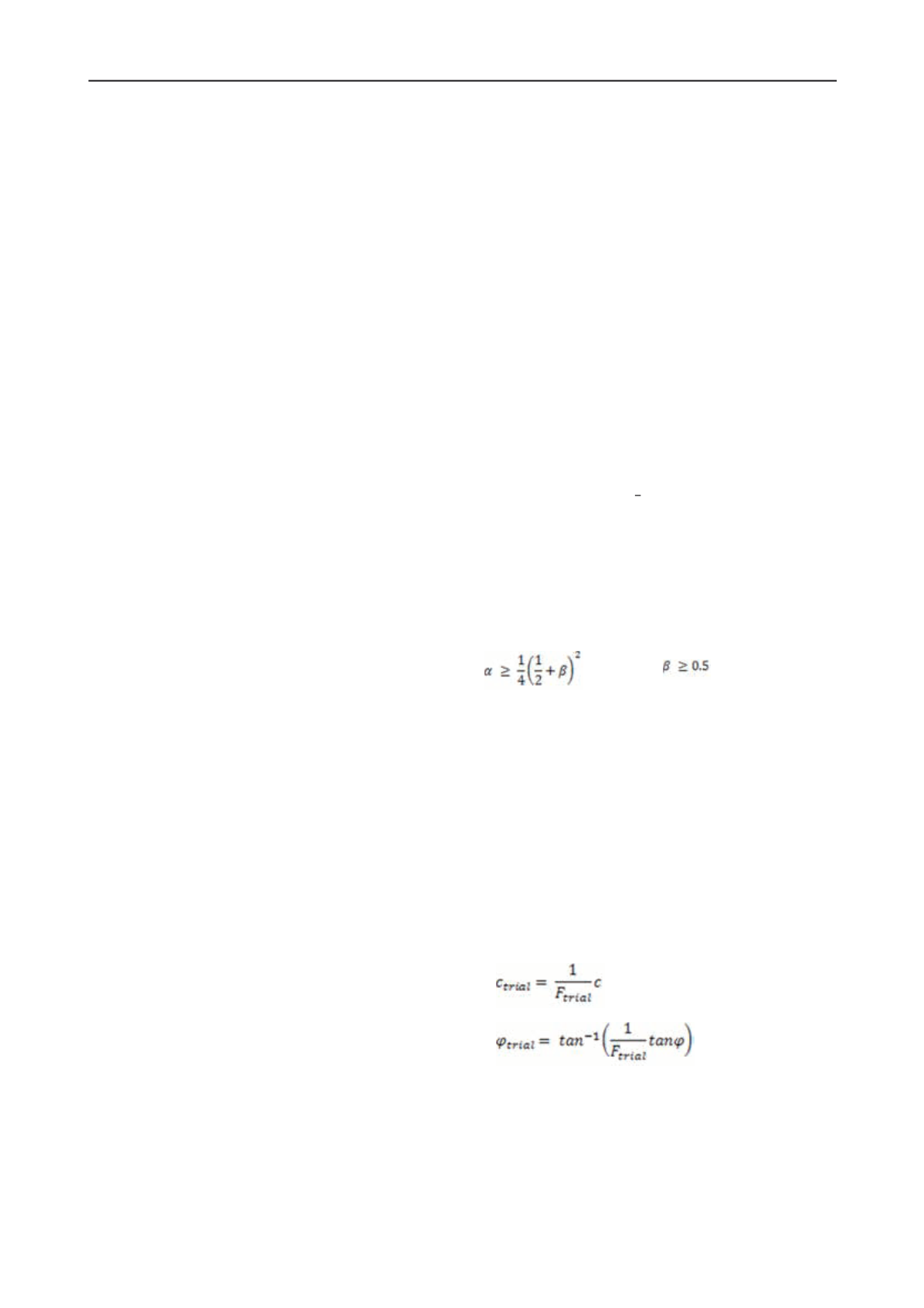
t is the time step. The coefficients
α
and
β
determine the accuracy of the numerical time integration and in
order to obtain a stable solution, the following conditions must
be satisfied
(3)
For dynamic calculations, the silent or absorbent boundaries
are created using viscous boundaries (dampers) to avoid stress
wave reflections and distortion in calculation results based on
the method described in Lysmer and Kuhlmeyer (1969). Excess
pore water pressure during dynamic loading can be generated
by considering undrained behavior of the soil but there are
limitations with liquefaction analysis.
For estimating factor of safety, the code uses strength
reduction technique (Matsui and San 1992) available as an
inbuilt option. In the technique, a
factor of safety
is taken as a
factor by which the soil shear strength is reduced to bring the
slope on the verge of failure. The concept is used in the slope
stability analysis in which a number of simulations are run for
trial
factor of safety
(
F
trial
) with shear strength parameters, i.e.,
cohesion (
c
) and angle of internal friction (
φ
) are reduced as
below:
(4)
(5)
The following section provides results of the static (factor of
safety) and dynamic numerical analysis of the dam section
under static and dynamic loading conditions without and with
provision of Geosynthetics as seepage barrier.
4 RESULTS OF THE ANALYSIS
For the analysis, a 10 m high homogeneous dam section with
1V:2H (U/S) and 1V:3H (D/S) slopes and top width of 5 m is


