996
Proceedings of the 18
th
International Conference on Soil Mechanics and Geotechnical Engineering, Paris 2013
3.4
Exploring micromechanics analytically
The contributions by
Shao et al. (2013)
and by
Caicedo et al.
(2013) both present theoretical developments.
Shao et al. (2013)
provide an analytical evaluation of the effect of pore water
pressure on the effective stress in the soil skeleton for saturated
and unsaturated media. Even though the developments are
certainly correct, the objective and conclusions of this study
appear somewhat obscure to the reporter.
The paper by
Caicedo et al. (2013)
reports an interesting
theoretical development regarding grain crushing – which is of
particular relevance when granular materials are used in
engineering structures such as paved roads, railroads and
highway embankments. The analytical model developed by the
Authors aims to predict the evolution of the grain size
distribution during loading. As an example, Fig. 13 shows the
evolution of the grain size distribution predicted by the model
after a very high number (up to one million) of loading cycles.
The model uses the theory of poly-disperse mixtures proposed
by De Larrard (2000), and predicts grain breakage by
combining the geometrical relevance of a size class of grains
with a statistical distribution of strength (given by a Weibull
distribution). When a particle breaks, the size of its fragments is
determined through a Markov process. The combination of
these elements appears to capture grain breakage successfully –
the application of this model to experimental results is shown to
give very good agreement. It is the Authors’ contention that
their model is a valid alternative to DEM, which can also deal
with grain crushing but is computationally very expensive.
Figure 13. Evolution of the grain size distribution for different number
of loading cycles
(Caicedo et al. 2013).
3.5
Engineering applications for energy production
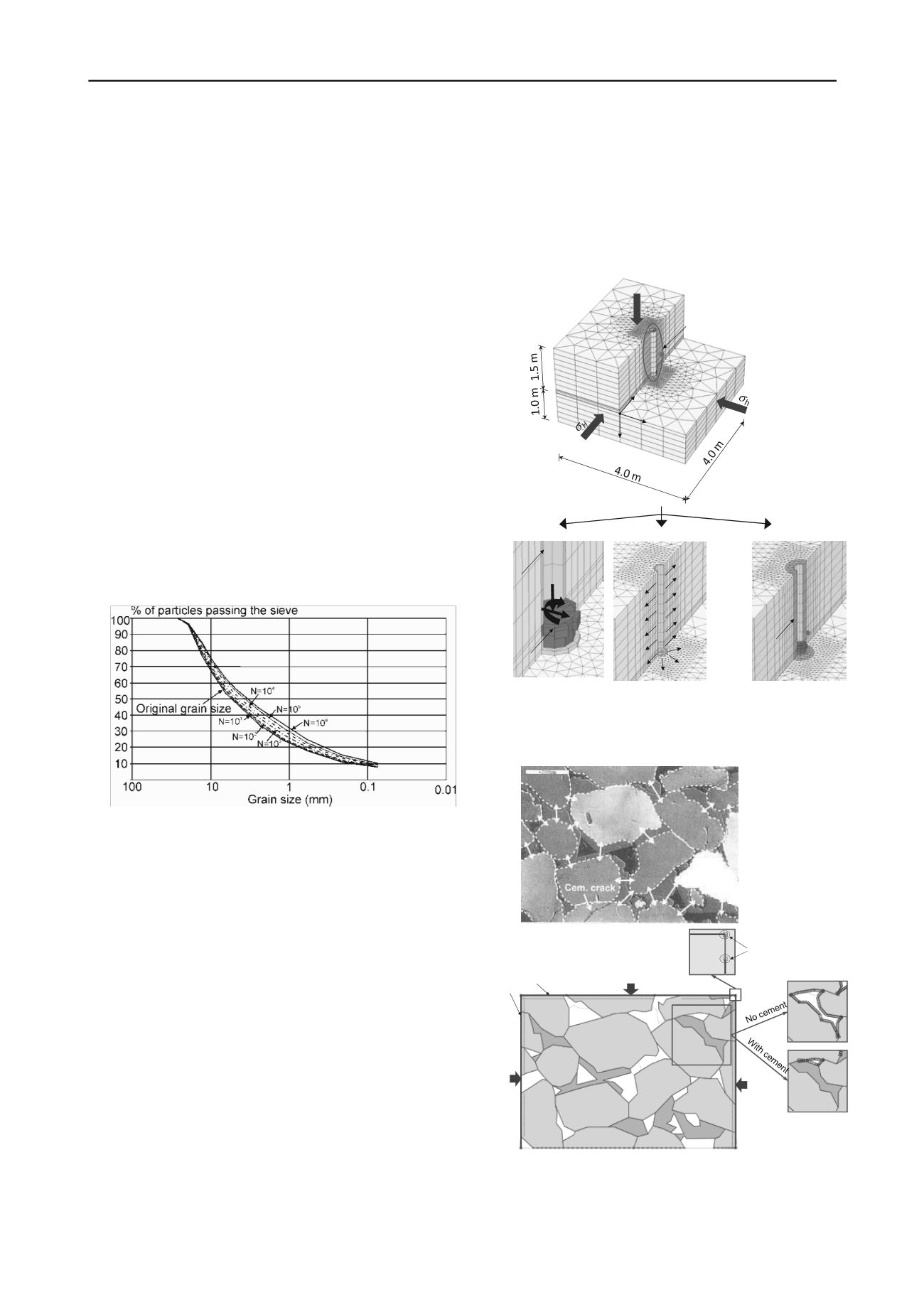
Interestingly, there is only one contribution to this session
making use of the Finite Element Method (FEM). This is the
numerical study by
Khoa et al. (2013)
, which tackles the
analysis of the damage induced by drilling and coring
operations in the rock surrounding a wellbore. This is a two-
scale analysis, in that a large scale 3D FE model is first used to
simulate the stresses induced by drilling and coring (see Fig.
14); these stresses are then injected into a 2D micro scale FE
model, the geometry of which is directly built on experimental
SEM observations of well cemented sandstone. The results
show that the micro FE model is able to pick up mechanisms of
failure that simply do not feature in the macro-scale continuum
model.
When going to the smaller scale analysis, the Authors
implicitly assume that a Mohr-Coulomb elastic perfectly plastic
model is capable of reasonably describing the stress state at the
micro scale. It should be mentioned that the paper does not give
any detail as for the determination of the mechanical parameters
used in the analysis at the micro scale. Moreover, strong
assumptions are made on the geological history (
e.g
., the grain
skeleton carries the load before getting cemented – which
means that as soon as unloading occurs, the inter-granular
cement gets loaded in tension and fails).
The approach adopted by Khoa and coworkers is certainly
original and interesting. However, although the analysis
presented in this study is indeed performed at two different
scales, it should be stressed that the only link between the two
scales is the stress in one point.
Figure 14. Full 3D FE modeling of different loads due to drill bit
torque and axial load, mud-flow into formation and temperature
change within one radius from wellbore wall
(Khoa et al. 2013).
Figure 15. Cathodoluminescence SEM picture (top) from Storvoll &
Bjorlykke (2004) and equivalent 2D micro FE model (bottom) used
for studying induced damage around a wellbore during drilling and
coring operations
(Khoa et al. 2013)
.
WOB
F
bit
From drill bit
Drill bit
Mud cake
TOB
From
temperature
T within 1
radius from
wellbore side
From mud
v
Borehole
(r ×h : 0.108 × 1.5 m
infiltration of
mud-fluid
y
A
y
z
x
A
Vertical stress,
V
Horizonatl stress,
h
Horizonatl stress,
h
Pore pressure,
u
Rotation
fixities
Beam
elements


