987
Technical Committee 104 /
Comité technique 104
3
RESULTS AND DISCUSSIONS
3.1
Bearing Capacity
Figure 6 shows the relationships between load and settlement on
the footing. At a given settlement, the ground with more layers
of geocell is indeed of higher bearing capacity. Given 0.5 times
of the footing width (i.e., 0.5B) being the tentative design
settlement, the model tests show that the bearing capacities of
the ground reinforced with one-layer and three-layer geocell
mattresses are 1.4 and 2.2 times of the natural ground, without
any reinforcement.
The increase of bearing capacity with the geocell
reinforcement could be in line with the finding (Rajagopal et al.
1999) that the geocell filled with soil as an integrated material
equivalently becomes a cohesive material, and in the meanwhile
the angle of internal friction remains more or less the same as
the sand infills
. Therefore, in use of the Terzaghi’s
bearing
capacity theory (see the textbook of Das 1999), the extra
material cohesion adds the overall bearing capacity to the
ground. More importantly, unlike the shear strength contributed
by the frictional behavior becoming nominal as the effective
normal stress is reduced significantly with the increase of pore
pressure, the soil strength contributed by cohesion is
independent of external stress and water pressure, or it should
come to existence regardless of external stress condition.
60
50
40
30
20
10
0
0
25
50
75 100 125 150 175 200 225
Bearing load (kPa)
Footing settlement, s/B (%)
Without reinforcement
With one-layer geocell reinforcement
With three-layer geocell reinforcement
Figure 6. The relationships of load and settlement in the three
model tests.
3.2
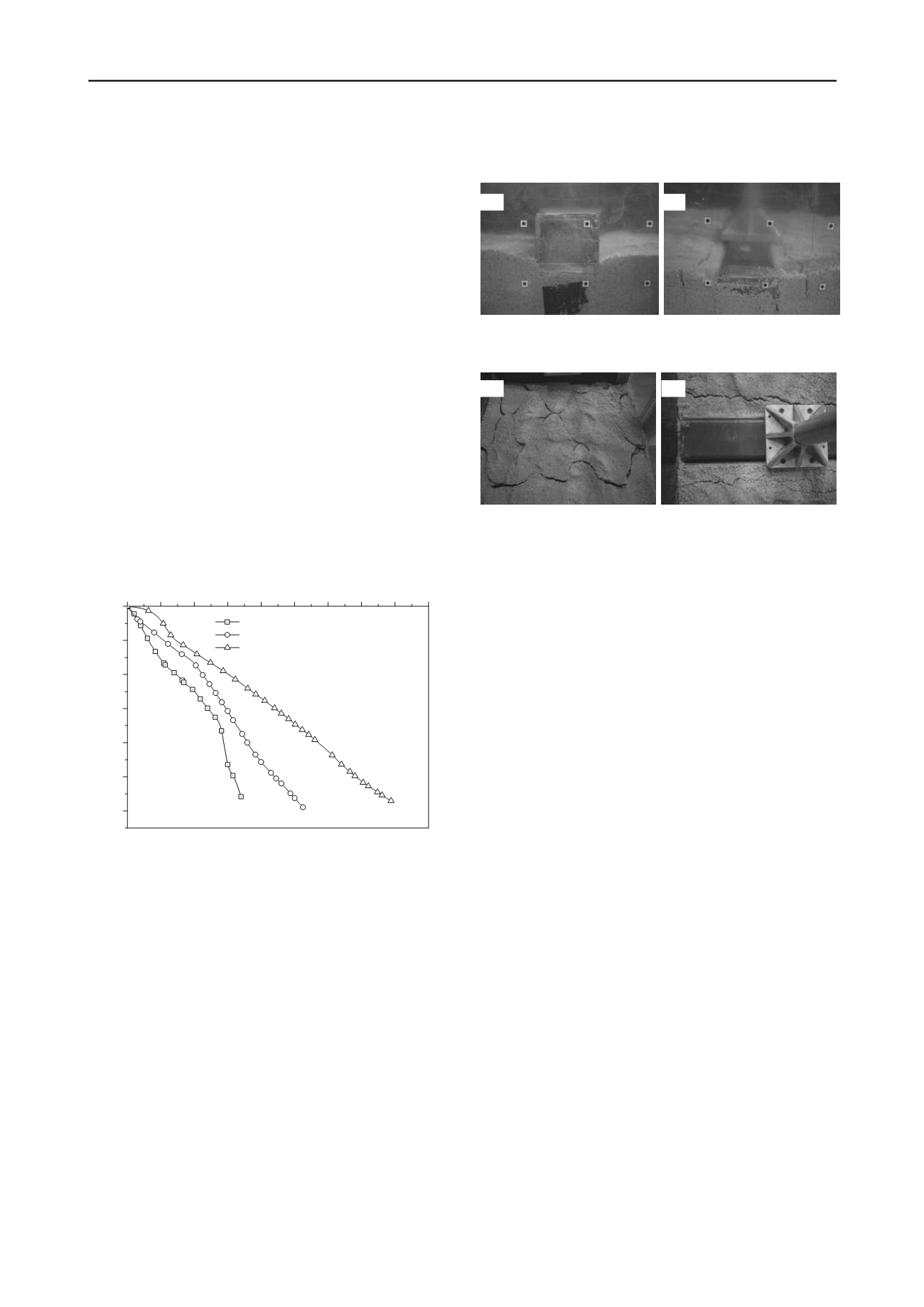
Tension cracks
Figures 7 and 8 show the model ground surface with and
without the geocell reinforcement. For a “natural” ground
without reinforcement, major tension cracks were observed very
close to the footing. On the other hand, tension cracks in the two
reinforcement tests were found located much further away from
the footing, developing within the soil inside of the two ends of
the geocell mattress.
The development of cracks close to the footing in the non-
reinforcement test should be caused by the excessive pore water
pressure excited in the soil due to external loading. As the
lateral soil pressure less than water pressure, the tension crack
should start developing. However, as the soil is reinforced by
geocell, the deformed geocell under the footing tends to shrink
the size of pockets, resulting in a large passive earth pressure
that is larger than the water pressure, and therefore, the
development of tension cracks is not allowed around the footing
with the geocell reinforcement. This also possibly explains that
the cracks would develop within the soil at the two ends of the
geocell mattress, because the level of deformation in geocell is
relatively small and the corresponding passive earth pressure is
not large enough to compensate the excited pore pressure in the
water-immersed ground.
Figure 7. The side view of the model ground surface: (a) with
geocell mattress; (b) without geocell mattress.
Figure 8. The top view of the model ground surface: (a) with
geocell mattress; (b) without geocell mattress.
3.3
Ground surface settlement and heave
Figure 9 shows the ground surface settlement at different
distances from the footing captured with LVDTs. In the three-
layer geocell model, the ground surface tends to settle in a
relatively large area, owing to the geocell-soil mattress acting as
an integrated system. Simply speaking, the geocell-soil
composites far away from the footing were pulled down owing
to the geoc
ell’
s structure, causing the ground settlement also
observed relatively far from the footing.
On the other hand, for the natural ground without the geocell
reinforcement, the soil adjacent to the footing was pushed
upwards because of soil failure occurring right under the footing
that would have formed a failure surface because of different
levels of soil movement. It is worth noting that this mechanism
and pattern in the ground deformation is well documented in a
bearing capacity test (Das 2007).
The ground deformation captured with LVDTs is on the
same page of the displacement field suggested by the PIV
system, as shown in Figure 10. For the natural ground, the PIV
displacement vector (Figure 10b) was pointing upwards near the
ground surface, but at the same locations, the downward
displacement vectors (Figures 10a) were observed as the ground
was reinforced by geocell.
It is worth noting that the
displacement fields of the reinforced ground are relatively
random compared to the natural ground, which should result
from the fact that the surface processed by PIV is neither a
completely reinforced soil nor a completely un-reinforced soil,
as the boundary condition of the geocell structure shown in
Figures 3 and 4.
4 CONCLUSIONS
This paper summarized the experimental work of using geocell
in ground improvement under an intense rainfall condition,
which recently recurs with an increasing rate owing to climate
change and extreme weather. The result shows that the
installation of geocell can indeed effectively improve the
bearing capacity of the loose-to-moderate ground subject to
high water content as a result of intense rainfall. The increased
bearing capacity should possibly result from the
“equivalent
Tension crack
Tension crack
Tension crack
Footing
(a)
(b)
(a)
(b)


