982
Proceedings of the 18
th
International Conference on Soil Mechanics and Geotechnical Engineering, Paris 2013
2 PILE SPECIFICATION
To produce a pile and pile loading system capable of high
quality bored pile behavioural simulation a wholly new design
was required of both the pile and the pile loading system.
2.1
Pile Cross Section
Researchers in the past have used a single wall to represent a
series of piles to simplify the problem to 2D plane strain (White
and Bolton 2004), while others have used square piles to
simulate the behaviour of circular piles.
Such solutions are not suitable for the problem type given
the inherent 3D nature of the problem and the significant edge
effects when using a plane of symmetry respectively. As such a
semi-circular design was deemed most appropriate to provide
the correct 3D stress and strain field around the pile.
Figure 1. Schematic cross section of plane of symmetry pile.
2.2
Axial Load Measurement
Shaft friction piles in the centrifuge have previously been
shown to produce inaccurate mechanisms for piles in sands.
The effect of shear band dilatancy on lateral stresses conditions
means that neither the load nor the mobilisation strain along the
shaft can be replicated concurrently (Lehane et al 2005).
To remove this error and to investigate a worst case scenario
of an end-bearing bored pile in sand, the shaft was sleeved
against friction.
Following on from this it was therefore only necessary to
measure the load at the pile head and base to ensure that the
sleeving was working.
In an attempt to reduce the errors associated with pile
bending on axial load measurement load cells situated along the
pile centroid were considered a suitable option.
2.3
Loading System
The pile loading system was designed to ensure that loading
remained through the centroid of the cross section and
simulated a bored pile. (This system is described in detail in
Williamson 2013).
2.4
Final Specification
The final specification was therefore set based on the
requirements described:
Pile to be semi-circular in cross section
Axial load measurement at head/base
Smooth face of shaft
Pile must remain in contact with symmetry plane
Loading through pile centroid
Load measurement along pile centroid
Loading to simulate bored pile behaviour
3 PILE DESIGN
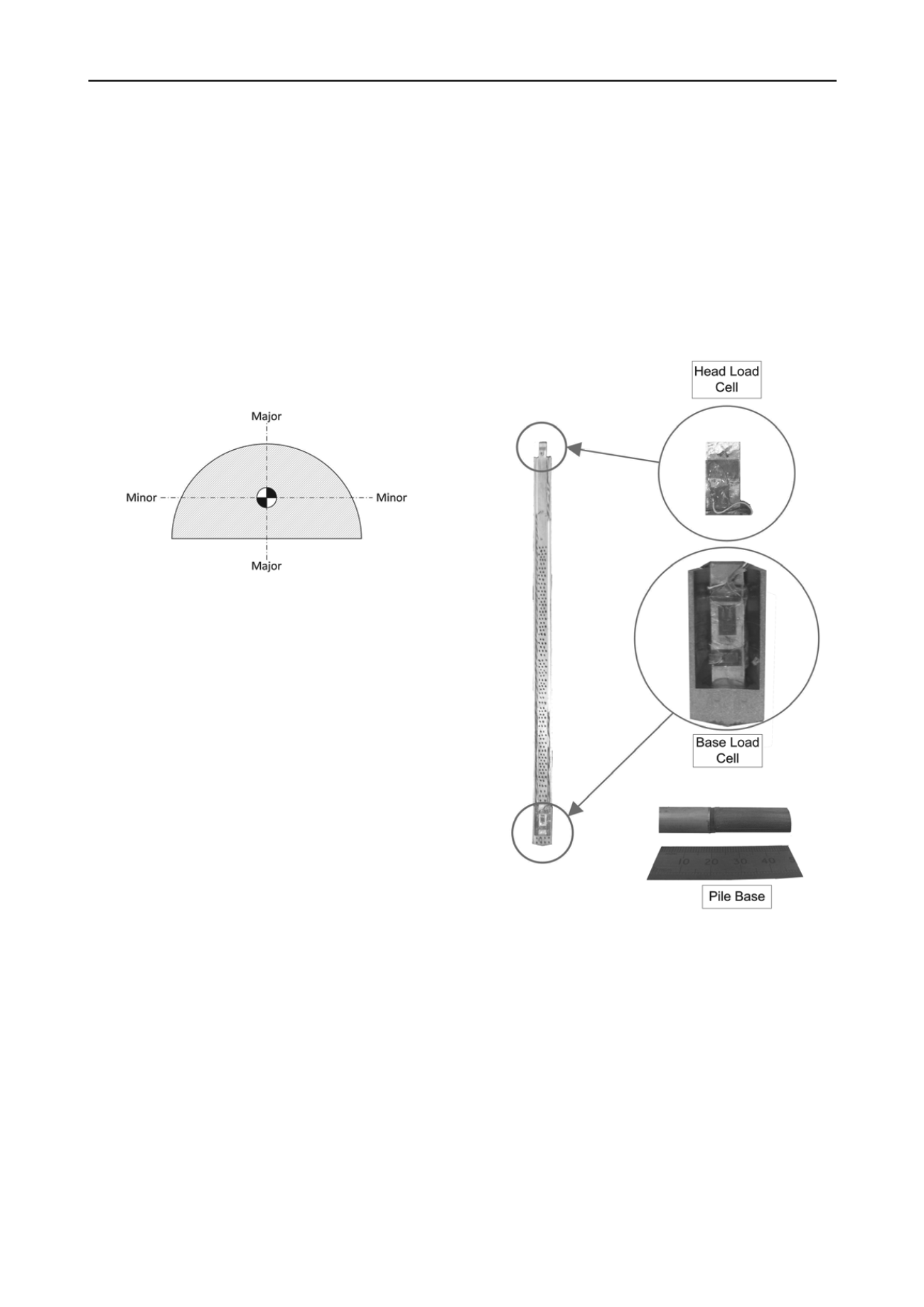
The final pile design is shown in Figure 2.
3.1
Pile Body
The pile body was machined from 2014-T6 aluminium, with
aluminium strain gauged load cells attached at the head and the
base. The pile was 15 mm in diameter and had an overall length
of 355 mm including the base and load cells.
3.2
Load Cells
The load cells were connected as full Wheatstone Bridges
with 4 No 350 Ω strain gauges used, 2 active and 2 inactive.
These load cells are situated precisely on the centroid of the
pile and connected securely between the pile shaft and base.
Figure 2. Final pile design.
3.3
Calibration
The pile load cells were calibrated before and after being
affixed into the piles. This was to investigate the effect of
bending during calibration resulting in the considerable free
length of the pile which has previously found to be an issue
(Marshall 2009).
A new calibration setup was designed to better replicate the
effective lengths in the centrifuge (~75 mm), which were small
in comparison with the overall free length of the pile (355 mm).
A comparison in the calibration factors between a load cell
calibrated individually and the same load cell within the pile is
shown in Figure 3. Clearly the agreement between the
calibration factors was good, and hence the system was then
taken forward to be used in the centrifuge where the effects of
high acceleration loads could be tested on the pile.


