983
Technical Committee 104 /
Comité technique 104
4 CENTRIFUGE SETUP
4.1
Centrifuge Package and Instrumentation
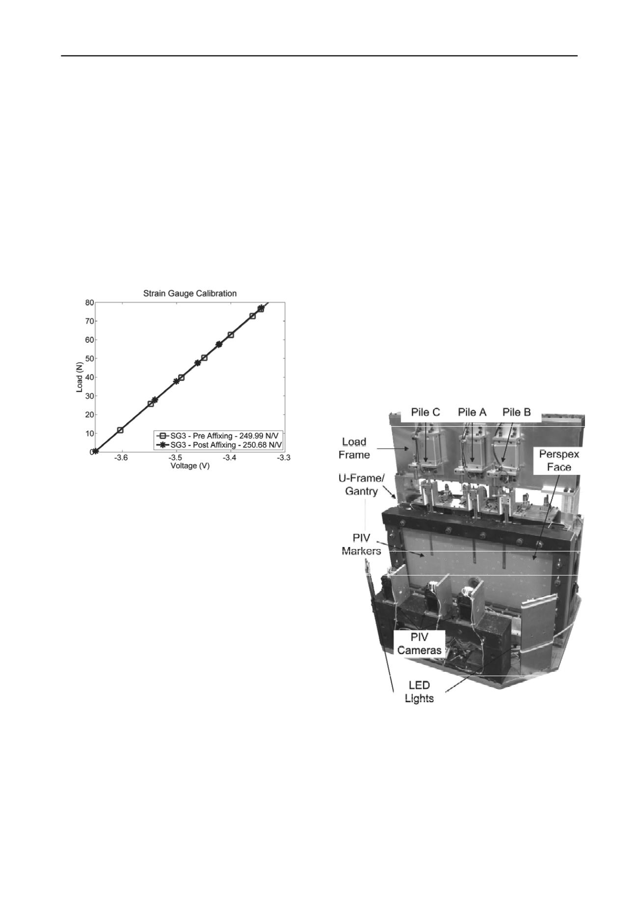
The centrifuge setup consisted of a strongbox, with a loading
frame/system and PIV cameras/lights (see Figure 4). The
strongbox had a Perspex face against which the piles rested, a
steel U-frame and an aluminium back, which provided very
high stiffness boundaries around the soil.
The PIV markers were calibrated against known target
positions. The pile displacements measured through PIV, were
also monitored with linear variable differential transformers
(LVDT’s).
To verify the values provided by the head and base load
cells, Novatech F259 Miniature Diaphragm 1 kN Loadcells
were attached to the loading system so that the change in head
load could be measured independently.
Figure 3. Pile calibration – before affixing to the pile body and after
affixing to the pile body.
4.2
Sand
The piles were placed firmly against the Perspex face and the
sand rained down over them. Fraction E Leighton Buzzard
Sand was used in the experiments at a relative density of 76%
±2%.
4.3
Experimental Procedure
Piles A and B (see Figure 4) were used to provide data on the
effects of tunnelling on bored piles, whereas Pile C was used to
provide details of the pile capacity and load settlement response.
The centrifuge was accelerated slowly to the desired 75g,
with photographs being taken from each of the PIV cameras at
various stages. The pile loads were monitored during the
acceleration phase after which loads were added to the pile
heads using a specially designed loading system, which applies
only the dead load of a pile cap for Piles A and B.
Pile C had a different loading system which also did not
apply any load until the desired 75g had been reached. This pile
also had a pile cap but with a loading pin capable of applying a
head beyond that of the cap dead weight.
All the piles were sleeved to the base (for details see
Williamson 2013) so that only the base component was a factor
in the pile loading.
5 RESULTS
5.1
Load Cell Response
The response of the load cells to the changing head load for Pile
C is shown in Figure 5.
Clearly the comparison between the commercially available
Novatech head load cell and the response of the new strain
gauged load cells is very good compared with the ideal 1 in 1
slope. No greater than 8% variation between the different types
of load cell is found.
The variation between the head and base load cell response
is relatively constant at around 80 N between 420 N and 1000N.
It was found that the pile toe began to move away from the face
slightly at 1000 N and hence the divergence is likely to be
attributed to some high level bending to the base load cell.
Piles A and B operate at working loads of between 100 and
120 N depending upon the experiment. Within this range the
variation between the change in head and base loads is small,
but the incremental loading is shown to be linear. This would
perhaps indicate slightly higher amounts of bending on the head
load cell. The calibration factors for the head load cells though
linear were slightly less consistent throughout the tests than the
base load cells. It is thought that their shorter length and the
slight inconsistency in the contact point between the pile cap
and the load cell could have affected the calibration factor,
though it was shown to vary by no more than 10 % throughout
the test series.
Figure 4. Centrifuge setup – illustrating the piles, loading system and
PIV setup.


