504
Proceedings of the 18
th
International Conference on Soil Mechanics and Geotechnical Engineering, Paris 2013
Proceedings of the 18
th
International Conference on Soil Mechanics and Geotechnical Engineering, Paris 2013
0
5
10
15
20
25
30
-15 -10
-5
0
5
10
15
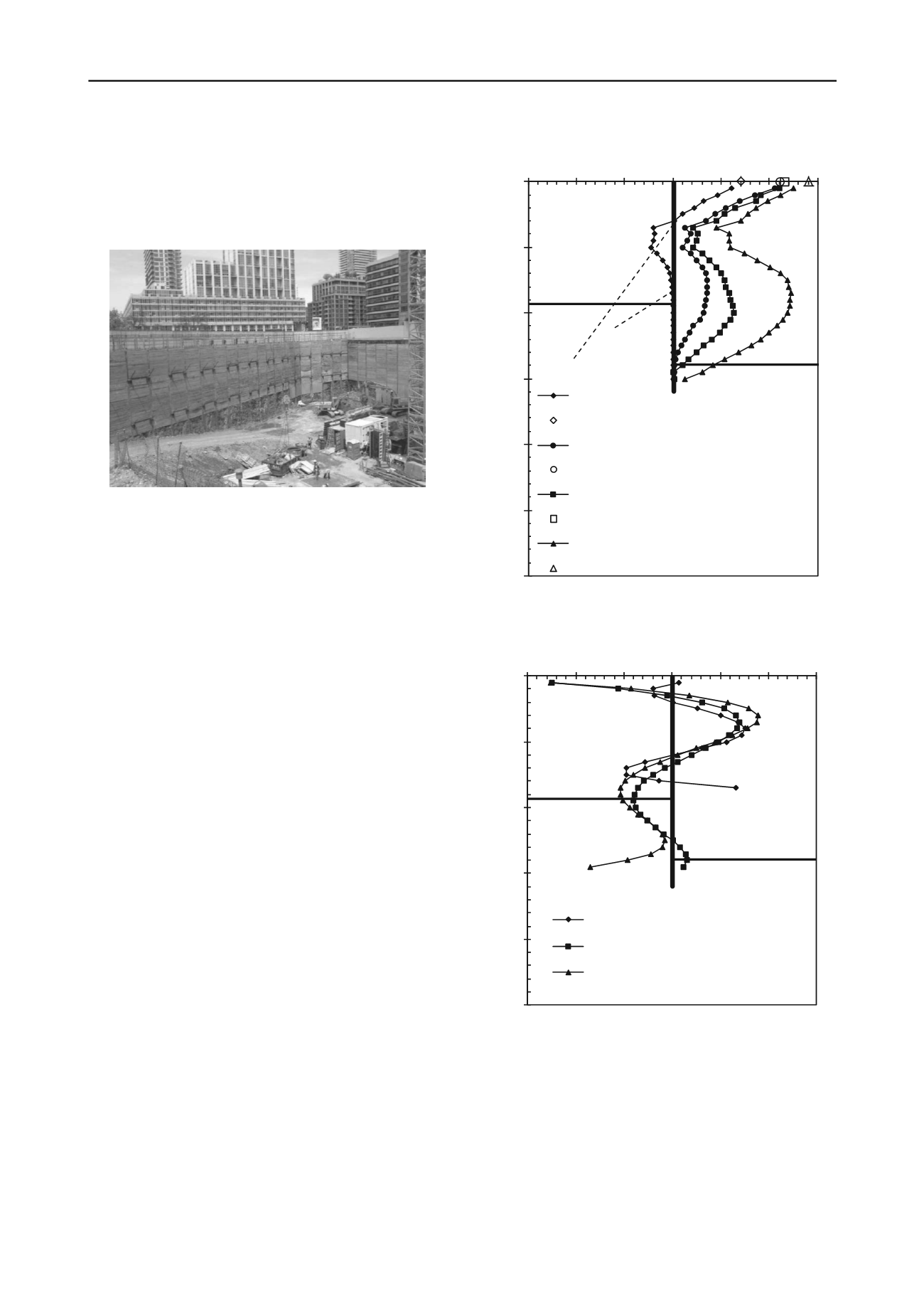
Depth (m)
Lateral Deflection (mm)
Inclinometer after upper tieback installed
Reflective target after upper tieback installed
Inclinometer after lower tieback installed
Reflective target after lower tieback installed
Inclinometer 1 d after excavation to bottom
Reflective target 1 d after excavatio to bottom
Inclinometer 11 mafter excavation to bottom
Reflective target 11 m after excavation to bottom
Excavation
Level
Bedrock Surface
Tieback
tiebacks. The test load was 133% of the design load and
maintained for 10 minutes. All tiebacks except three tiebacks
met the PTI criteria. The three tiebacks could not reach the test
load due to the broken wires. A lower design load was used for
the three tiebacks. Detailed discussions on the tiebacks are
presented by Cao and Peaker (2011).
Figure 1. Outlook of soldier piles with wood lagging supported by
tiebacks
0
5
10
15
20
25
-600 -400 -200
0
200 400 600
Depth (m)
BendingMoment (kN/m)
Inclinometer after upper tieback installed
1 d after excavation to bottom
11 m after excavation to bottom
ExcavationLevel
Bedrock Surface
Two inclinometers were installed inside the soldier pile walls
during the pile installation. The inclinometers were monitored
during and after the excavation. Figure 2 shows the monitoring
results of one inclinometer including the reading taken after
upper and lower tieback installations, 1 day after the excavation
to bottom, and 11 months after the excavation. The lateral
deflections measured by reflective targets installed at the top of
soldier piles are also shown in Figure 2. The measurements of
reflective targets are consistent with the inclinometer
measurements.
3 BENDING MOMENT FROM WALL INCLINOMETER
MEASUREMENTS
The inclinometer measurements have been used to estimate wall
bending moments by some researchers (Poh et al. 1999). The in-
wall inclinometers provide a direct measurement of the rotation.
These measurements can be subsequently converted into wall
deflections along the wall. The wall curvatures
can be derived
from the wall deflection data. The second differential equations
of the wall deflection will give the
along the wall. The
bending moment M can be computed from
using the
following equation (West, 1993)
M =
I
= KI(d
2
y/dx
2
)
(1)
where E is the elastic modulus of the wall, I is the inertia
moment of the wall, y is the lateral deflection of the wall and x
is the distance along the wall.
Using Microsoft Excel spreadsheet, the inclinometer
measurements were fitted with a sixth- degree polynomial and
double differentiation of this polynomial gave
. The coefficient
of determination value obtained during the curve fitting ranged
from 0.98 to 0.99, indicating minimal error during the process
of curve fitting. The Young’s moduli of 0.4 MPa concrete and
H-beam W610x82 were taken as 2.8 GPa and 200 GPa,
respectively. The sum of concrete EI and H-beam EI was used
in the calculation of the bending moment. Figure 3 shows the
bending moments deduced from the wall inclinometer
measurements. Higher bending moments were observed at the
locations of tiebacks. However, significant high values of
bending moments were obtained near the ground surface, which
is against the typical distribution of bending moment along a
cantilever beam. This could be an error inducted in the double
differentiation of the wall deflection. Further study using a
Figure 2. Lateral deflection of soldier pile wall
Figure 3. Wall bending moments deduced from inclinometer
measurements
higher degree polynomial and a defined boundary condition is
required.
4 FINITE ELEMENT BACK-ANALYSIS
The finite element program Phase 2 (version 8.0) was used in
the back-analysis. The program can be used to simulate
excavation in soil and rock under plane strain condition. Six-
node triangle elements were used to model the soil and bedrock
media. The soldier pile wall and tiebacks were modelled by


