512
        
        
          Proceedings of the 18
        
        
          th
        
        
          International Conference on Soil Mechanics and Geotechnical Engineering, Paris 2013
        
        
          *(
        
        
          1)/
        
        
          *( 1)/
        
        
          (1 )


            p


            p


            d


            d


            k


            k


            k


            k


            c


          (1)
        
        
          where γ is a key dimensionless factor, which is a function of
        
        
          wedge angle of cutter , elastic constants and plastic strength
        
        
          parameters.


            *


            *


            *


            u


            i


            = E, or G , q , , , ,


          (2)
        
        
          and ξ is defined as dimensionless elasto-plastic (E-P) radius
        
        
          while ξ* reach critical value where brittle fracture occurs on this
        
        
          E-P interface. Thrust force, therefore, can be estimated using the
        
        
          indentation pressure P and indentation force F as seen in Figure
        
        
          2 schematically.
        
        
          p
        
        
          p
        
        
          n (K 1)/K
        
        
          p
        
        
          *
        
        
          p
        
        
          p
        
        
          (n 1) K
        
        
          P 1
        
        
          1
        
        
          q K 1 K n


          (3)
        
        
          n 1
        
        
          i
        
        
          d
        
        
          F (3 n)
        
        
          P(
        
        
          )
        
        
          tan


          β
        
        
          (4)
        
        
          d


            Intrinsic


            flaw


          Core
        
        
          Plastic zone
        
        
          Elastic zone


          2a
        
        
          *


            r


          Indenter
        
        
          F
        
        
          E-P
        
        
          interface
        
        
          , max


            x


          X
        
        
          y
        
        
          Figure 2. Schematic normal indentation fracture
        
        
          2.2


            Generalized trust system


          This study presents a generalized trust system of cutter head
        
        
          globally by taking each different types of individual cutters into
        
        
          account locally with respect to different methods (TBM, ST,
        
        
          and PJ) and geological conditions (rock, soil, & gravel). Figure
        
        
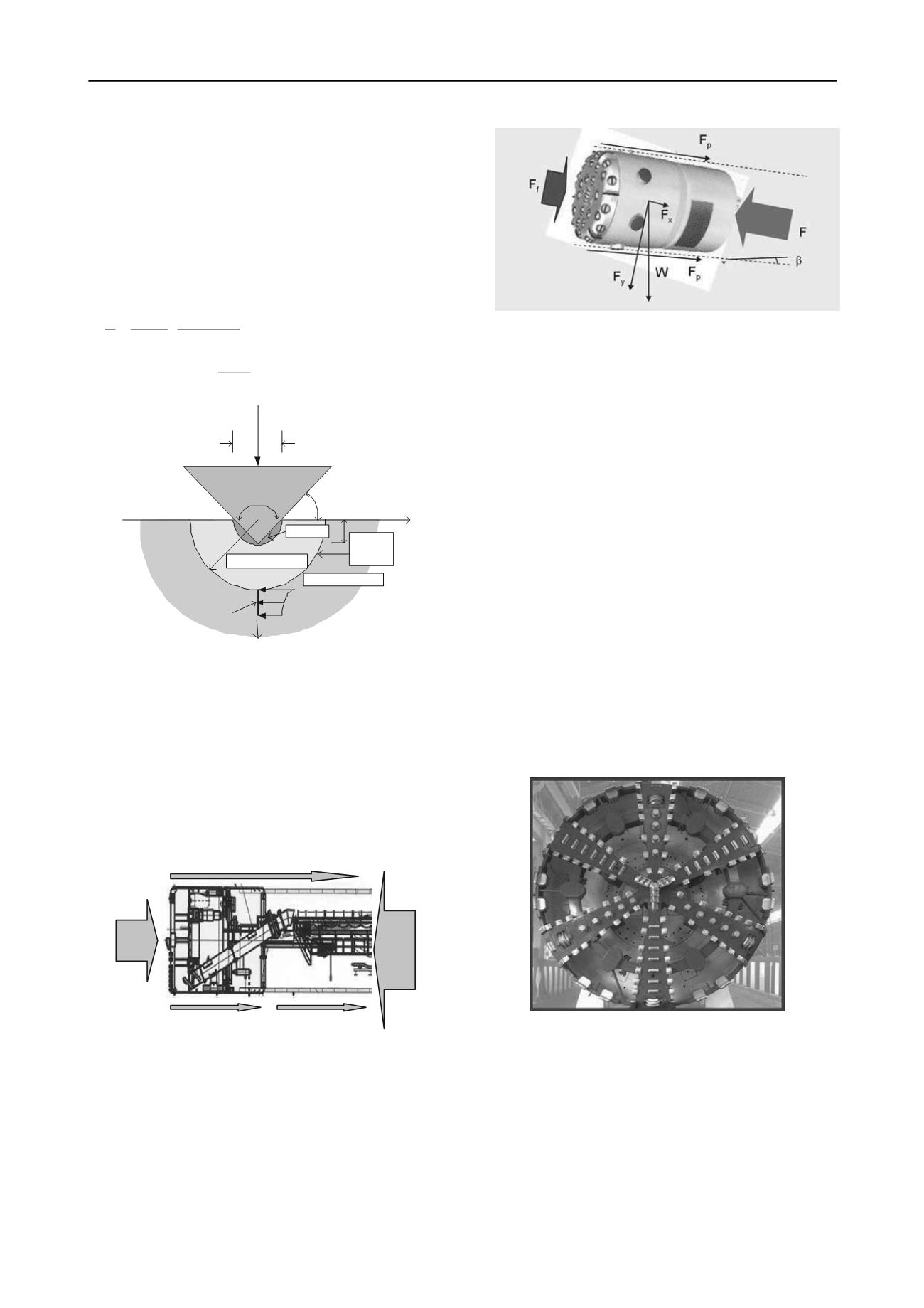
          3a and 3b show the total trust force F, which is consists of front
        
        
          resistance F
        
        
          f
        
        
          and lateral resistances F
        
        
          p
        
        
          including both F
        
        
          p,m
        
        
          for
        
        
          machine itself and Fp,p for pipes.
        
        
          f
        
        
          p,m p,
        
        
          F F F F


          p
        
        
          (5)
        
        
          p,p
        
        
          F
        
        
          p,m
        
        
          F
        
        
          f
        
        
          F
        
        
          F
        
        
          p
        
        
          F
        
        
          Figure 3a. Trust force system
        
        
          Figure 3b. Trust force system with inclined angle
        
        
          Therefore, Ff (kN) is estimated from different types (nj) of
        
        
          cutters fj and water/earth pressure Ps (kN/m2):
        
        
          m
        
        
          f
        
        
          j
        
        
          j
        
        
          s
        
        
          j 1
        
        
          F n f P


          A


          (6)
        
        
          where A is cross area of cutter head (m
        
        
          2
        
        
          ).
        
        
          This paper presents an analytical estimation to deal with
        
        
          different mechanical cutting methods (tunnel boring machine,
        
        
          shield tunnel and pipe jacking), construction types (earth
        
        
          pressure balance, slurry pressure balance, thick-mud), and
        
        
          geological conditions (soil, gravel and rock) by generalizing
        
        
          their total thrust system. The straight-line thrust is calculated for
        
        
          either wedge- or conical-typed cutters of tunneling machine. In
        
        
          this generalized work, the upper bound and lower bound of trust
        
        
          are highlighted for the warning situations for risk assessment.
        
        
          3 CASE STUDY
        
        
          3.1


            Case I:  Taoyuan tunneling project in Taiwan


          In addition, the in-situ data of trust in shield machine
        
        
          (Taoyuan tunneling project) is presented to confirm with. It
        
        
          depicts a favorable agreement for the estimation of thrust in this
        
        
          study as shown in Figure 4 (cutter head), and Figure 5 (results)
        
        
          with respect to normal cutting as well as abnormal conditions
        
        
          (point a and b shown in Fig.5) once the in-situ data out of the
        
        
          theoretical boundaries.
        
        
          Figure 4. Cutting head in field for shield tunnel project