496
Proceedings of the 18
th
International Conference on Soil Mechanics and Geotechnical Engineering, Paris 2013
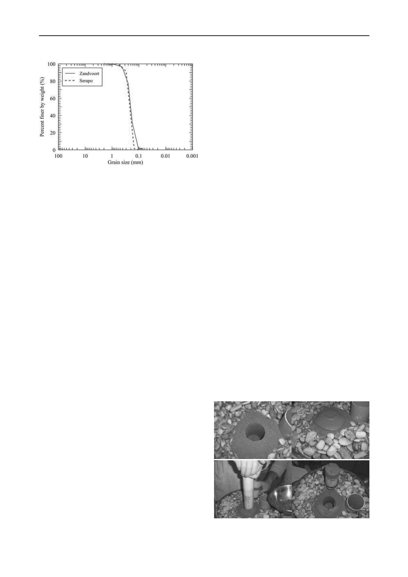
Figure 1. Grain size distribution of the Zandvoort and Serapo sands .
To construct the 11.5 m deep CSM panels (2.4 x 0.55 = 1.32
m
2
sectional area) the 1-Phase system was chosen, therefore the
grout was injected on both downward and upward stroke. The
grout composition adopted for the panel production was
characterized by a water-to-cement ratio
w/c
= 1.12 and a binder
factor
α
= 509 kg/m
3
of natural soil. The cement used was a
special composite cement especially produced for ground
improvement applications.
After mixing, several wet-grab samples were collected from
the fresh panels at about 2,0 m from the ground level and
immediately sealed into watertight tins (inner diameter of 98
mm and height of 113 mm).
3 MATERIALS AND TESTING PROGRAMME
The
wet-grab
samples collected from the site (in the following
referred as “SWGS”) were cured under controlled condition
(room temperature of about 20°C and at a relative humidity >
95%.) for 40 and 125 days in order to measure also the time
influence on the unconfined compressive strength (UCS) of the
treated soil. Before testing, the wet-grab samples were cored to
provide specimens of 37 and 54 mm in diameter with an aspect
ratio of 2. Finally, the specimens were trimmed to regularize the
bases and wrapped with plastic film to prevent moisture loss.
Laboratory soil-binder mixtures were prepared at the same
grout/sand ratio used on site, according to the treatment
parameters evaluated from the elaborated machine production
data. The grout and the soil were first prepared separately and
then mixed together for 10 minutes using a high power mixer to
produce the stabilized soil, according to the recommendations
for laboratory mixed specimens provided by the Japanese
Geotechnical Society (JGS0821-2000).
The stabilized soil was then poured into plastic moulds 50
mm in diameter and 100 mm in height using the No
Compaction technique (simply consisted in filling the mold) to
realize the
laboratory mixed specimens
(referred as “LS”).
Past experiences of sandy soil stabilization (Yoshimura et al,
2009, Grisolia et al, 2010, Bellato et al., 2012) showed the
following occurrences related to water drainage conditions:
The physical properties (water content and wet density)
of sandy soil collected from the site, especially when taken
below the groundwater table, typically are different from the
initial in-situ conditions, due to the loss of fine particles and
water during sampling and transportation to the laboratory;
Bleeding, i.e. separation of water from the soil-binder
mixture, generally occurs immediately after the mixing
process in the bowl and causes the sedimentation of some
amount of cement at the surface;
Every molded sample usually shows the occurrence of
bleeding phenomena, that inevitably leads to a reduction in
the specimen’s height;
In addition, when the mixture is taken from the bowl for
molding operations, separation among constituent materials
may be observed. This further increases the variability in
terms of amounts of binder, water and sand of the samples.
Moreover, during in-situ soil treatments, some water
drainage may also arise depending on the type of mixing
procedure adopted and the specific subsoil conditions. In
particular, sedimentation mechanisms in the liquid soil-binder
slurry mixture may develop just after the passage of the
mixing tools and some amount of water can be radially
drained away into the surrounding permeable sandy layers
(Yoshimura et al, 2009).
To simulate the effects of water drainage on the mechanical
properties of stabilized soils in the laboratory an original
experimental set up was designed and used (Figure 2).
The apparatus was essentially composed of a watertight
container in which a cylindrical sand core, reproducing the site
conditions, is placed and surrounded by a gravel filter, with
installed an open pipe for water level control (Figure 2a).
A cylindrical cavity was then prepared and filled with the
stabilized soil just after the mixing operations (Figure 2b). After
a time span equal to that adopted on site before sampling, a
laboratory wet-grab specimen was retrieved (Figure 2c and 2d).
The two types of specimens, i.e. laboratory (“LS”) and
laboratory wet-grab
(“LWGS”), were cured at 20°C and at 95%
relative humidity in curing tanks and removed from the moulds
just before the test.
In order to investigate the influence of the sand type and
mineralogy on the performance of the stabilized material, a
marine soil namely Serapo Sand (Figure 1) was also used to
prepare laboratory and laboratory wet-grab specimens.
The experimental investigation mainly consisted of
unconfined compression tests. The specimens were tested at
different curing times, ranging from 7 to 125 days.
To evaluate the influence of the physical and chemical
characteristics of the natural soils (Zandvoort and Serapo sands)
SEM (Scanning Electron Microscope) and EDS (Energy
Dispersive Spectroscopy) analysis were carried out.
A CamScan MX2500 electron microscope, equipped with a
EDAX EDS (energy dispersive X-ray spectrometer) system was
used to determine both the morphology and chemical
composition of the grains. Two small samples for both sands
were first oven dried at 40°C for 24 h and then coated with a
layer of carbon using an high-vacuum evaporative coater to
prevent the accumulation of electrostatic charges at the surface
during irradiation.
4 RESULTS AND DISCUSSION
The results of the unconfined compression tests performed on
the three series of samples (SWGS, LS, LWGS) are presented in
Figure 2. Experimental set-up for laboratory wet grab specimens: a)
cavity preparation, b) mixture pouring, c,d) specimen retrieval.


