395
Technical Committee 101 - Session II /
Comité technique 101 - Session II
where H
T
:total thickness of the pavement structure (in), Ep:
equivalent modulus of pavement structure above the subgrade
(psi).
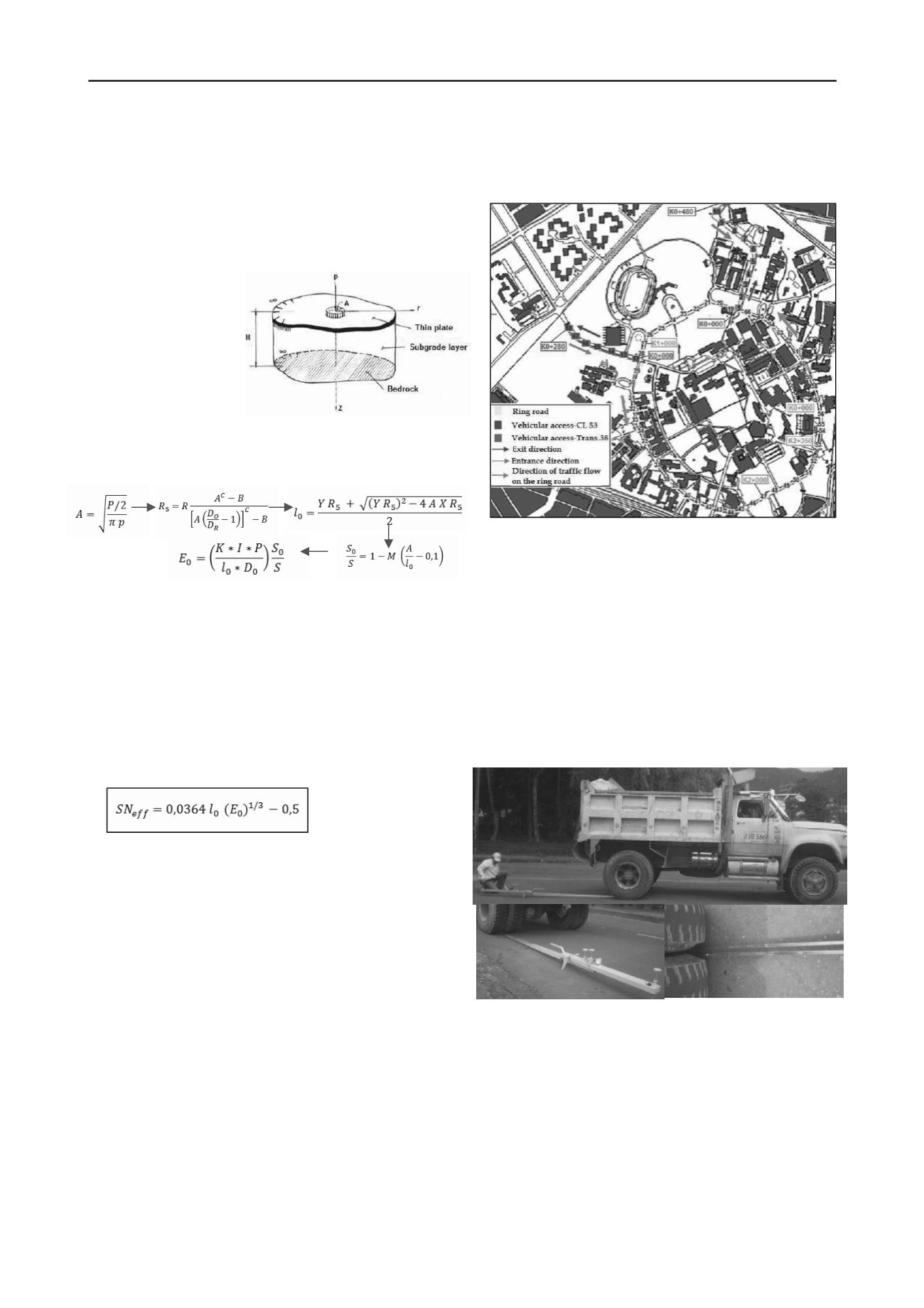
Figure 5. Methodology of Hogg Model for calculation of
subgrade modulus
3.2.
Hogg Model Methodology (for Viga Benke.)
In 1944, Hogg presented the mathematical solution of the model
which is known by his
name. This assumes that
the pavement layers are
characterized by a thin
plate with a certain bend-
ing stiffness.
The
subgrade
is
represented by an elastic,
linear, homogeneous and
isotropic medium (Figure
3).Hoffman,
in
1977,
presented the computerized
solution of the model, which is summarized below in Figure 5.
where A: radius of the contact circular footprint, P: load on the
double rim (1/2 of the load on back axle. Example 80 KN / 2 =
40KN),
p
: inflation pressure, R: distance which deflection D
R
is
measured, D
0
: maximum deflection, D
R
: deflection at a distance
R, R
5
: distance from the geometric center of the double rim along
until obtaining the relation D
R
/D
0
=0.5, lo: characteristic length of
the deflection basin, S
0
: stiffness for theoretical point load, S:
stiffness of the pavement, E
0
: modulus of subgrade (kg/cm
2
). I, K,
M, X, Y, A, B, C: numerical coefficients developed for the model
(see Ref 5).
The effective structural number (SN
eff
) is calculated depend-
ing on the characteristic length and the modulus of subgrade as
shown below:
..….. (2)
where E
0
: modulus of subgrade (MPa), l
0
: characteristic length
(cm).
It is possible to calculate the equivalent modulus of pavement
layers by means of Ullidtz proposal.
4
STUDY AREA
The study area is located on the campus of the Universidad
Nacional de Colombia-Bogotá, it includes three sections of
flexible pavement structure which are part of the road network of
the university, these are: the main Ring road with a length of 2375
meters, vehicular access Calle 53 with length of 480 meters and
vehicular access Transversal 38 with a length of 280 meters.
The deflection measurement was taken in 66 points, as shown
in Figure 4.The area presented various types of damage including
longitudinal failures, fatigue cracking (alligator cracking),
interventions of asphalt patching, edge cracking and small
potholes. Moreover vegetation influence is quite evident
negatively causing transverse and block cracks by the action of the
root system.
Figure 4.Study area. Road network at Universidad Nacional de Co-
lombia -Bogotá
Figure 3. Scheme of Hogg mode
Hoffman, Mario. 1985
5
MEASUREMENT DEVICES
5.1 Benkelman beam
Benkelman beam (Figure 5) is a device which operates on a
simple lever arm principle, the unit consists of a rigid support
beam, pivot, one or two measurement probe beams and dials
indicator. It is a convenient and practical device for measuring
deflection of flexible pavements under the action of wheel loads
and works in conjunction with a suitable loaded vehicle (back axle
loaded with 80 KN).The probe beam is placed between the dual
tires of a test vehicle, and deflection is measured as the vehicle
passes over the test area to beyond the end of the probe beam.
The measurements were taken at 0 (Lo), 75, 150 and 300 cm,
the end of the two probe beams were separated 25 cm each other,
which means the readings were estimated at 0, 25, 75, 100, 150,
175, 300 and 325 cm from the center of load application. The
temperature was taken with a manual thermometer.
Figure 6.Benkelman beam (two-part probe beam)


