273
Technical Committee 101 - Session I /
Comité technique 101 - Session I
Proceedings of the 18
th
International Conference on Soil Mechanics and Geotechnical Engineering, Paris 2013
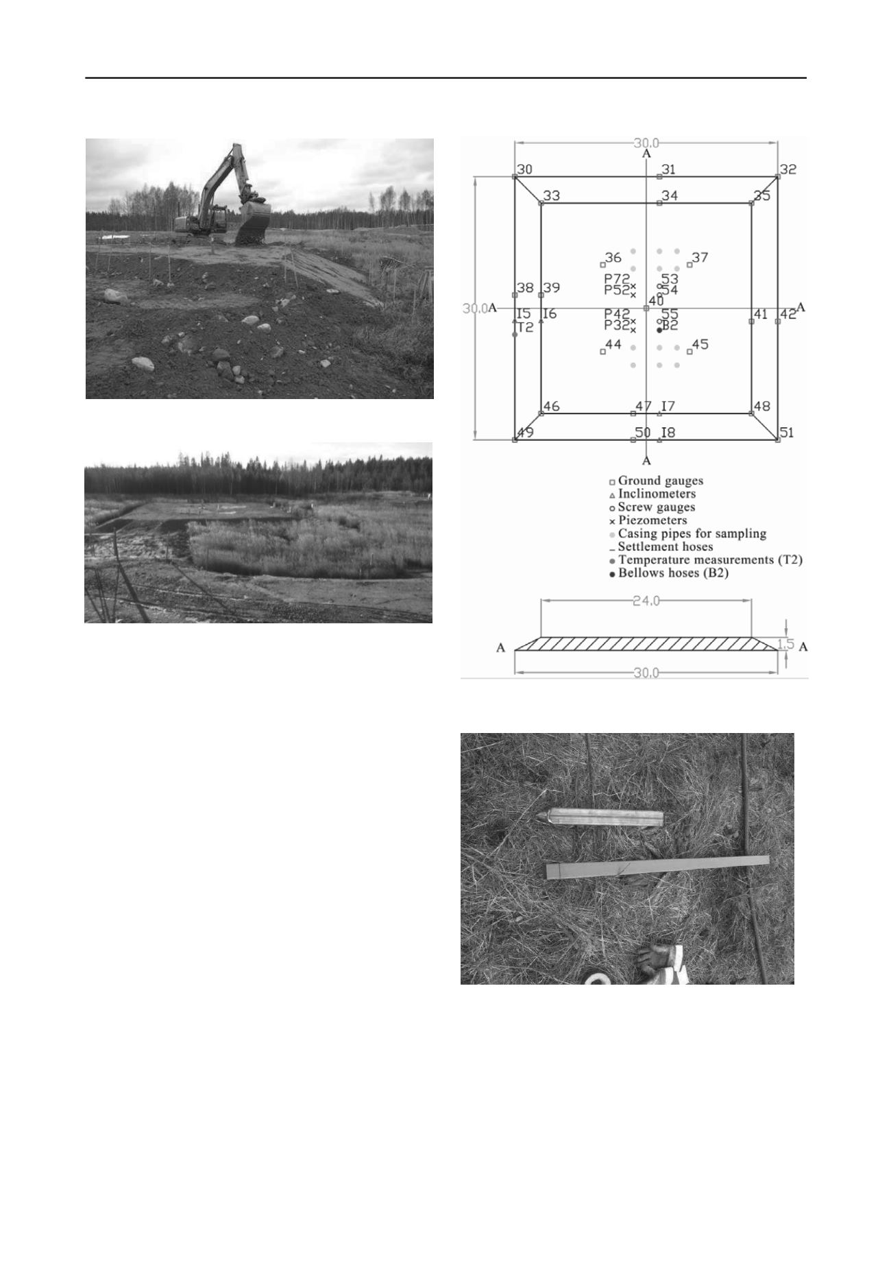
Figure 5 Construction up to height 1.5 m for embankment 1
.
Figure 6 Finished construction of embankment 2 (1.5 m height).
Photograph taken about two years after finished the construction.
Equipment for measuring movements (deformations), pore
pressures and soil temperatures have been installed below and
beside the two embankments, see figure 7 for embankment 2.
For measuring horizontal movements inclinometer tubes of
PVC with a square cross-section were used. This equipment has
been designed for measurements in soft clays but had never
before been tested in sulphide soils, figure 8.
Figure 7 Plan of measuring equipment and cross-section of embankment
2 (in meters).
Figure 8 Inclinometer tube of PVC with square cross-section with steel
point at the end.
4 FIELD MEASUREMENTS
In figure 9 is presented one example of measured vertical
movements from settlement hoses and settlement gauges,
embankment 2 about 1.2 years after construction. The
settlements are similar when comparing the two measuring
methods.


