244
Proceedings of the 18
th
International Conference on Soil Mechanics and Geotechnical Engineering, Paris 2013
Proceedings of the 18
th
International Conference on Soil Mechanics and Geotechnical Engineering, Paris 2013
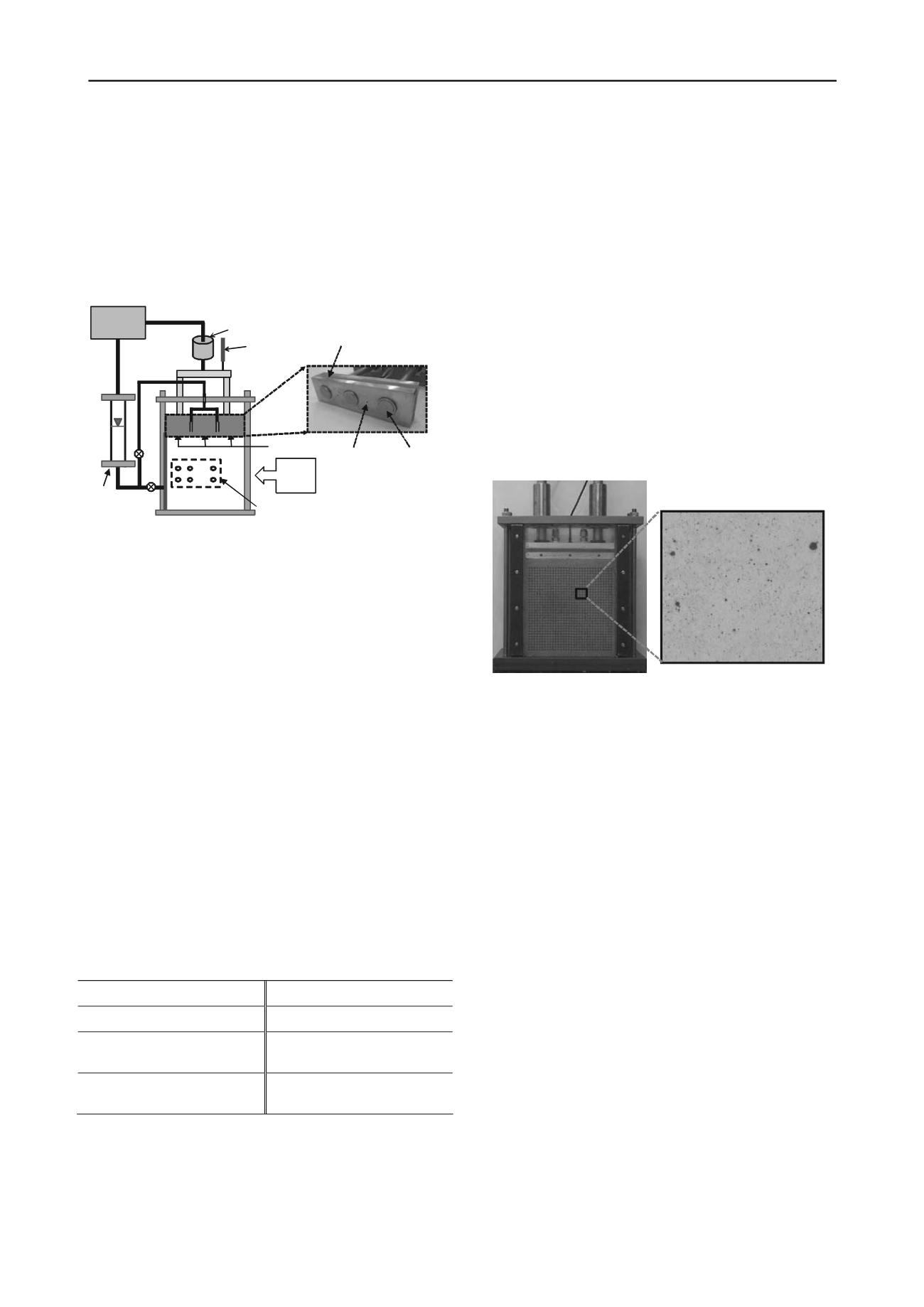
different vertical locations and 3 different horizontal locations
are installed to obtain the pore pressure distributions from the
drain boundary. And 3 earth pressure gauges are mounted on
the top rigid loading platen, which will provide the total vertical
stress variations. A plate of porous plastics used for drain
materials are placed on the top of the specimen for vertical
drainage and at the side for horizontal drainage. The pressure
lines were connected to top and side of model box, which allow
saturation of the sample by applying back pressure and dissipate
pore water.
Figure 1. Schematic diagram of developed consolidation test apparatus
Although the axi-symmetric condition with vertical drains is
in reality, the developed model box simulates plane strain
condition to provide a more favorable environment to perform
digital image analysis. So, if necessary, further study for
modification of the interpretations of the results will be
followed.
2.2. Soils
The reconstituted EPK Kaolinite was used for the test
specimen. Its index properties are summarized in Table 1. The
clay specimens were created using the slurry consolidation
techniques described by Sheeran and Krizek (1971). Dried EPK
Kaolinite powder was mixed with de-aired water until the water
contents reach twice of the liquid limit of the Kaolinite. The
prepared slurry was poured into a large consolidometer of
which diameter is 0.3 m. The slurry was loaded with 10 kPa
increments until the applied vertical pressure reaches 100 kPa.
After reaching the target pressure, the vertical stress was kept
constant for 7 to 10 days for the complete consolidation. After
removing the vertical pressure, the sample was extruded
carefully from the consolidometer, wrapped in plastic films,
coated with paraffin wax, and stored in the controlled humidity
and temperature storage room until ready for use. The
maximum past pressures of the clay samples are determined as
about 100 kPa, from the oedometer test results.
Table 1. Index properties of reconstituted kaolinite
Liquid limit (%)
64.4
USCS
MH
Plasticity index (%)
21.8
Initial void ratio
1.56
Percent finer than #200
sieve (%)
98
Initial water contents
(%)
61.0
Specific gravity
2.55 Maximum past pressure
(kPa)
100
2.3. Test procedure
The test procedure with the developed device for consolidation
was summarized as; 1) trimming the reconstituted kaolinite
sample, 2) creating image patterns on the surface of trimmed
sample and 3) assembling test apparatus. Deformation analysis
through image processing is basically done by using two
different images taken at two separate times. For this process, a
random image pattern was created by spraying oil-based paint
on one side of specimen as shown in Figure 2.
After assembling the apparatus with specimen, back pressure
was applied for specimen saturation. Pore pressure parameter C
value defined as the ratio of excess pore pressure increment to
applied vertical total stress, higher than 0.97 was considered as
full saturation. For the consolidation test, vertical stress
increments by pneumatic pressure were applied on the top of
the specimen. Consolidation process was achieved by applying
vertical stress increment under undrained condition and then
opening drainage line. 3 total stress increments (initial stress to
100 kPa, 100 kPa to 200 kPa, and 200 kPa to 300 kPa) were
applied for both tests on horizontal drainage and vertical
drainage condition. Initiating consolidation by opening the
drainage valve, the values of pore water pressure and total
vertical stress are stored via the data logger, and images are
taken at regular time intervals, 10 seconds in the early stage of
consolidation and increasing time steps as consolidation
proceeds. A Nikon D90 digital camera, which has a resolution
of 4288 x 2848 pixels, was used to get photo images.
Earth pressure
gauge
Pore pressure
measuring points
Back pressure
reservoir
LVDT
Digital
Camera
Pneumatic Actuator
Compressor
Silicon
Earth pressure
gauge
1 3 5
2 4 6
Drainage
hole
Figure 2. Prepared sample in the assembled test apparatus
The completion of consolidation was confirmed by both
measuring pore pressure and interpreting time-settlement curve.
After completion of all consolidation tests, water contents at 25
locations for both tests of drained direction were measured. In
this study, to exclude the effect of stress history, final loading
step (200 kPa to 300 kPa of vertical stress increment) was
focused to be analyzed.
2.4. Digital image analysis
In the geotechnical application of the digital image analysis,
two major techniques have been widely used; digital image
correlation (Rechenmacher and Finno 2004) and particle image
velocimetry (White et al. 2003). Herein, the Particle Image
Velocimetry (PIV) technique was employed for the deformation
measurement because of its better performance in convergence
as well as the simplicity of the algorithm. To perform the image
analysis, a flat object is supposed to deform 2-dimensionally in
the plane of the image which can easily be satisfied in the
developed consolidation apparatus which describes plane strain
condition.
Kim et al. (2011) suggested a procedure determining
optimum image processing condition by statistically analyzing
the data of image analysis resulted from the original image of
test specimen and manipulated one. Following this procedure,
the lowest maximum error, which contains the value of
accuracy and precision (Taylor 1999), of approximately 0.002
mm in 90% confidence level was obtained when using PIV with
bi-square interpolation, 60 x 60 pixel subset size and 0.28 % of
vertical strain interval. As shown in Figure 2, the adopted image
in the test specimen is divided into 1024 (32×32) pixel subsets;
thus, providing 1024 displacement vectors at the center points
of the pixel subsets.


