138
Proceedings of the 18
th
International Conference on Soil Mechanics and Geotechnical Engineering, Paris 2013
12
-2
-1
0
1
2
3
4
Clay
Composite
Log Concentration (
g/L)
PAL
ES
Figure 14. Box plot comparisons of dichloromethane (DCM)
concentrations in collection lysimeters beneath composite lined
and clay lined cells in landfills in Wisconsin; ES = enforcement
standard; PAL = protective action limit (data from Klett 2006).
4.2.6
Vertical Barriers
A wide variety of vertical barriers have been used for
in
situ
hydraulic and contaminant containment applications,
including sheet-pile walls, grout curtains, concrete barriers,
geomembrane barriers, gravel-filled trenches, and slurry
based cutoff walls, such as soil-bentonite (SB), cement-
bentonite (CB) and soil-cement-bentonite (SCB) walls
(Mitchell et al. 2007). However, the slurry based vertical
cutoff walls probably are the most commonly used vertical
barriers for in situ containment of contaminants. Similar to
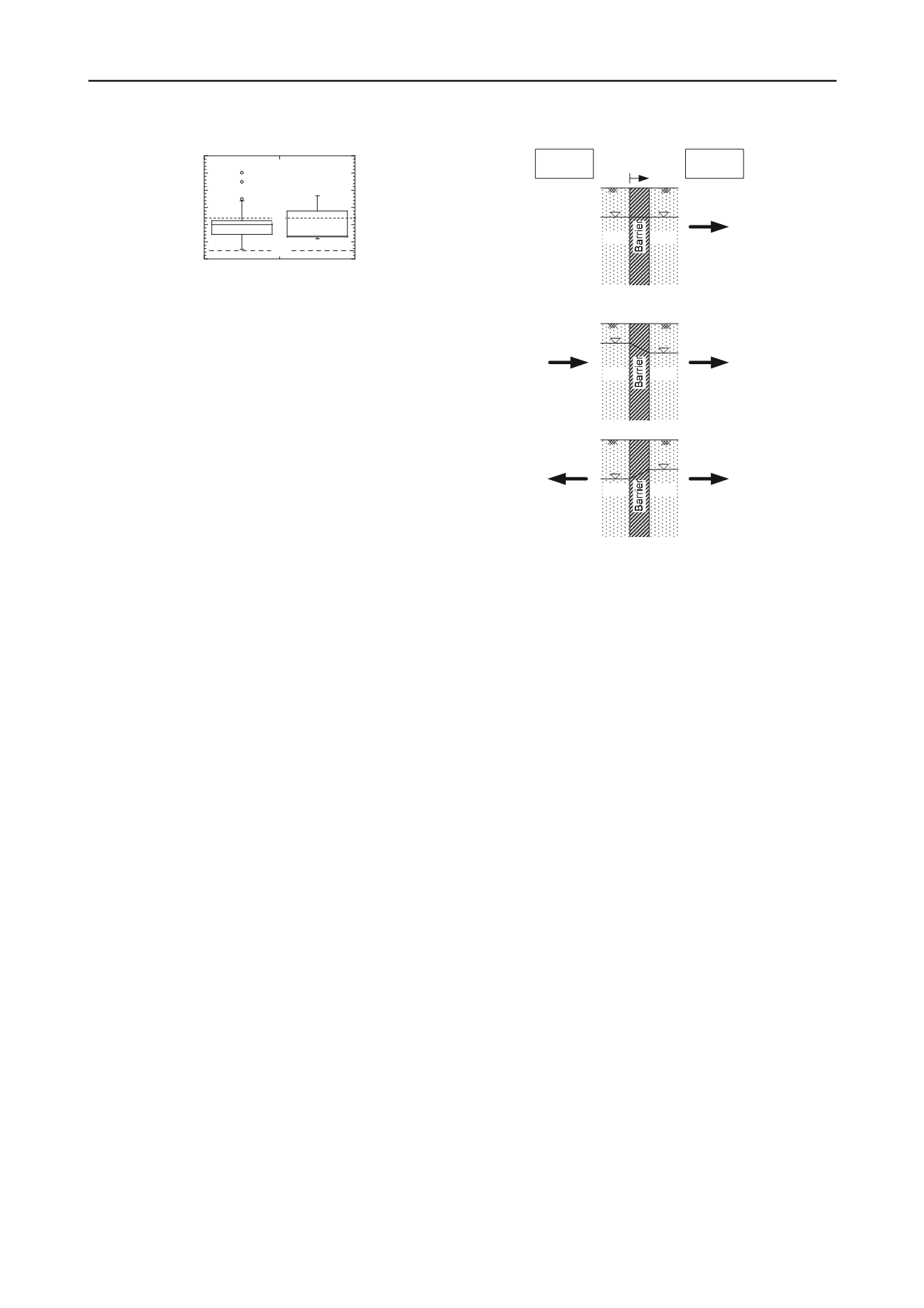
the case of horizontal barriers (Fig. 3), contaminant
transport through such vertical barriers can be categorized
into three possible scenarios as illustrated in Fig. 15,
viz.
,
pure diffusion (Fig. 15a), diffusion with positive (outward)
advection (Fig. 15b), and diffusion with negative (inward)
advection (Fig. 15c).
The pure diffusion scenario (Fig. 15a) exists when there
is no applied hydraulic gradient across the barrier. This
scenario would exist only in practice when there was little
or no local groundwater flow in the vicinity of the barrier
location prior to installation of the barrier, and no net
accumulation or depletion of water on either side of the
barrier during the operational life of the barrier. As a
result, the only possible transport process is diffusion from
the containment (inward) side of the barrier (
C
> 0)
towards the outside of the barrier (
C
= 0). As the
conditions for this scenario are not typically encountered in
practice, this scenario may be considered as a limiting
case.
The scenario for diffusion with positive (outward)
advection (Fig. 15b) exists when the local groundwater
level on the containment side of the barrier is allowed to
rise, e.g., via infiltration of precipitation, such that a
hydraulic gradient is established across the barrier in the
same direction as the prevailing concentration gradient,
i.e., from the containment (inward) side of the barrier (
C
>
0) towards the outside of the barrier (
C
= 0). Thus, both
advection and diffusion occur in the same direction, i.e.,
outward.
The scenario for diffusion with negative (inward)
advection (Fig. 15c) is analogous to the hydraulic trap
scenario represented in Fig. 3c, and occurs when the
groundwater level within the containment side is drawn
down, e.g., by pumping or passive drainage (e.g., French
drains), so as to generate an inwardly directed hydraulic
gradient to drive advective transport that counteracts the
outwardly directed diffusive transport, thereby minimizing
the net outward contaminant flux. Transport analyses for
this scenario have been reported by Shackelford (1989),
Manassero and Shackelford (1994), Devlin and Parker
(1996), and Neville and Andrews (2006).
(a) Diffusion without Advection
(Pure Diffusion)
(b) Diffusion with Positive Advection
(c) Diffusion with Negative Advection
Direction of
Advection
Direction of
Diffusion
> 0
= 0
> 0
= 0
> 0
= 0
+
x
Figure 15. Contaminant transport scenarios across vertical barriers
for in situ containment: (a) pure diffusion; (b) diffusion with
positive (outward) advection; (c) diffusion with negative (inward)
advection (modified after Gray and Weber 1984, Shackelford
1989, 1993, Manassero and Shackelford 1994, Devlin and Parker
1996, Neville and Andrews 2006, Sleep et al. 2006, Mitchell et al.
2007).
Although several studies have focused on evaluating
contaminant transport through slurry based vertical cutoff
walls (Gray and Weber 1984, Mott and Weber 1991a,b,
Manassero et al. 1995, Devlin and Parker 1996,
Khandelwal et al. 1998, Rabideau and Khandelwahl 1998,
Krol and Rowe 2004, Britton et al. 2005, Neville and
Andrews 2006, Malusis et al. 2010), only a few of these
studies (e.g., Mott and Weber 1991a,b, Khandelwal et al.
1998, Krol and Rowe 2004) were extensively experimental
studies focusing specifically on evaluating the diffusive
properties of contaminants in traditional (unamended) SB
backfills. In all of these studies, which were focused on
diffusion and sorption of organic chemicals (e.g., 1,4-
dichlorobenzne, 4-chlorophenol lindane, trichloroethylene,
and aniline), the results indicated that the values of
D
*
typically were reduced by a factor of only about two to
four relative to the corresponding values of
D
o
, and at most
were no more than an order of magnitude lower than
D
o
,
due, in part, to the relative high porosity values associated
with most SB backfills. Also, sorption of the organic
chemicals to the traditional (unamended) soil-bentonite
backfills typically was negligible (i.e.,
K
d
0) due to the
typically low organic carbon contents of the unamended
backfill materials (e.g., Malusis et al. 2010). These two
factors (i.e., relatively high
D
*
and negligible
K
d
)
combined with the typical inability to achieve backfill
hydraulic conductivity values lower than about 10
-10
m/s
(e.g., D'Appolonia 1980, Evans 1991, 1993, 1994, Filz and
Mitchell 1996, Shackelford and Jefferis 2000, Filz et al.
2003), suggest that the significance of diffusive transport
across vertical cutoff walls is likely governed largely by
the magnitude of the applied hydraulic gradient,
i
h
, across
the barrier, with diffusive transport becoming more
significant with decreasing magnitude in
i
h
(i.e., Fig. 15a).


