1302
Proceedings of the 18
th
International Conference on Soil Mechanics and Geotechnical Engineering, Paris 2013
2 SITE INVESTIGATION, GEOLOGICAL FEATURES
In central Germany, there are mainly landfill sites with mixed
soils with varying silt contents. Due to the technique used for
filling, dumped from a great height, the fill is deposited in
poorly compacted heterogeneous horizontal thin layers
(varved). These mixed soil man-made deposits are much more
compressible than natural soils. Particularly in the upper soil
layers down to a depth of 10 m, the soils are often arranged in a
very loose state. A reliable assessment of the interaction
between the structure and the subsoil is very difficult on mixed
dump soil.
Figure 2. The dump of Schleenhain
As a result of loose deposition or rather the heterogeneity of
the material and its density, the soil behavior is different from
natural deposits. Experiences and methods used with the
development of soft natural soil are not transferable to these
types of man-made deposits (Lausitzer und Mitteldeutscher
Bergbau – Verwaltungsgesellschaft 1999). The process of
conveying, transporting and dumping is the reason that the
deposit is locally marked by extreme material and density
heterogeneity in a very confined space. Due to the mixture of
cohesive fines and loose grain, these deposits consistently
characterized by a very strong sensitivity and the risk of loss of
strength due to plastification by water ingress.
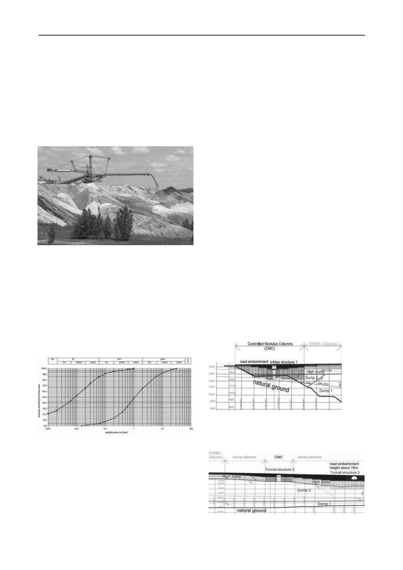
The soil investigation results from the fill show a large
variation in grain size.
Figure 3. Spread of grading curves of the dump soil (G.U.B. Ingenieur
AG 2010)
The following fractions have been used for the design of the
ground improvement for the new road, according to the
geotechnical report (G.U.B. Ingenieur AG 2010):
- 20% boulder clay
- 20% sands and gravels
- 25% tertiary clay
- 30% fine and medium sand
- 5% brown coal
This mixed-grain fill material represents almost the entire
typical soil in the mining area. Details on the natural soil with
boulder-clay and silt layers of the quaternary will not be
presented here.
Currently, the groundwater level has been lowered to at least
35 – 40 m below ground-level by the ongoing dewatering
operations of the daylight mining, whereupon the relatively
steeply running saturation lines of the depression cone have all
developed in tilted, grown border slopes. By the year 2100, a
static groundwater level should be reached after turning off the
pumps at an altitude of 125 m of about 15 m significantly below
the gradient and at least slightly below the lowest level of the
foundation of new embankments.
With w
n
= 10%...14%, the calculated current water content
under the influence of dewatering is in the normal range of
natural humidity. Laboratory tests showed a proctor density
about ρ
Pr
= 1.846 g/cm
3
, and a proctor water content about w
Pr
=
9.9% and thus good compression options.
Cone penetration tests from the landfill at up to ca. 20 m
depth vary mainly in the range of qc ~ 1.0 MN/m
2
...3.5 MN/m
2
,
which lead to the estimation of a stiffness modules
Es ~ 2 MN/m²...9 MN/m², with average = 5.5 MN/m², as
described in the geotechnical report.
It is a mixed-grain fill material (fine particle fraction >
20%...25%) in the earth-moist state. With water saturation a
plastification is possible, because of the fine particle fraction
and the storage of loose grains and mixed pseudo-cohesive soil.
In the event of plastification, the shear strength drops to about
50% of the baseline values.
3 PLANING OF THE SOIL IMPROVEMENT METHODS
The connection to the new B176 is located on the so-called
mainland area. This is characterized by the transition from
natural soil towards the central part of the road to the landfill
area. From this point of view it is a very challenging
geotechnical transition in the route. Other settlement issues are
arising from the different embankment height as a result of the
area conditions. Without the use of specially adapted ground
improvement methods, settlements of up to one meter could be
expected. In order to reduce settlements and to avoid critical
differential settlements, a special sequence and quality control
of soil improvement techniques was chosen at the transition
with the main land and the three structures.
Figure 4. Design section along the road centerline in the transition from
the main land (natural ground) to the landfill.
The following figure 5 shows the floating foundation of two
building structures on the 50 to 70 m thick fill deposit.
Figure 5. Design section of the tunnel structures crossing the up to 15 m
high embankment over the landfill


