2598
Proceedings of the 18
th
International Conference on Soil Mechanics and Geotechnical Engineering, Paris 2013
Proceedings of the 18
th
International Conference on Soil Mechanics and Geotechnical Engineering, Paris 2013
3 CONSTRUCTION AND BUILDING LAYOUT
In Figure 3,4 and 7 the lay out of the building and building
pit are shown. Because of the very deep excavation next to the
pile foundation of the existing building, much precaution had to
be paid to settlements and angular distortion (damage) of this
listed building. Also, the bending moments in the existing
wooden piles were a major concern. This resulted in a staged
excavation as shown in Figure 4. Note the different excavation
levels of the two excavations A and B, which cause an
asymmetrical load situation and displacements. An extra
complication was that the building site could only be accessed
through a narrow entrance in the eastern part.
Figure 3. Section C-C: new situation (note swimming pool at -3)
Figure 4. Schematic cross-section C-C, NAP = reference level
4 GEOTECHNICAL DESIGN
Because of the asymmetrical excavation and the need to assess
soil and building deformations, 2D FEM Plaxis calculations
were performed. In Figure 5 an example of the used model for
section C-C is shown(see Figure 7). Based on the deformations
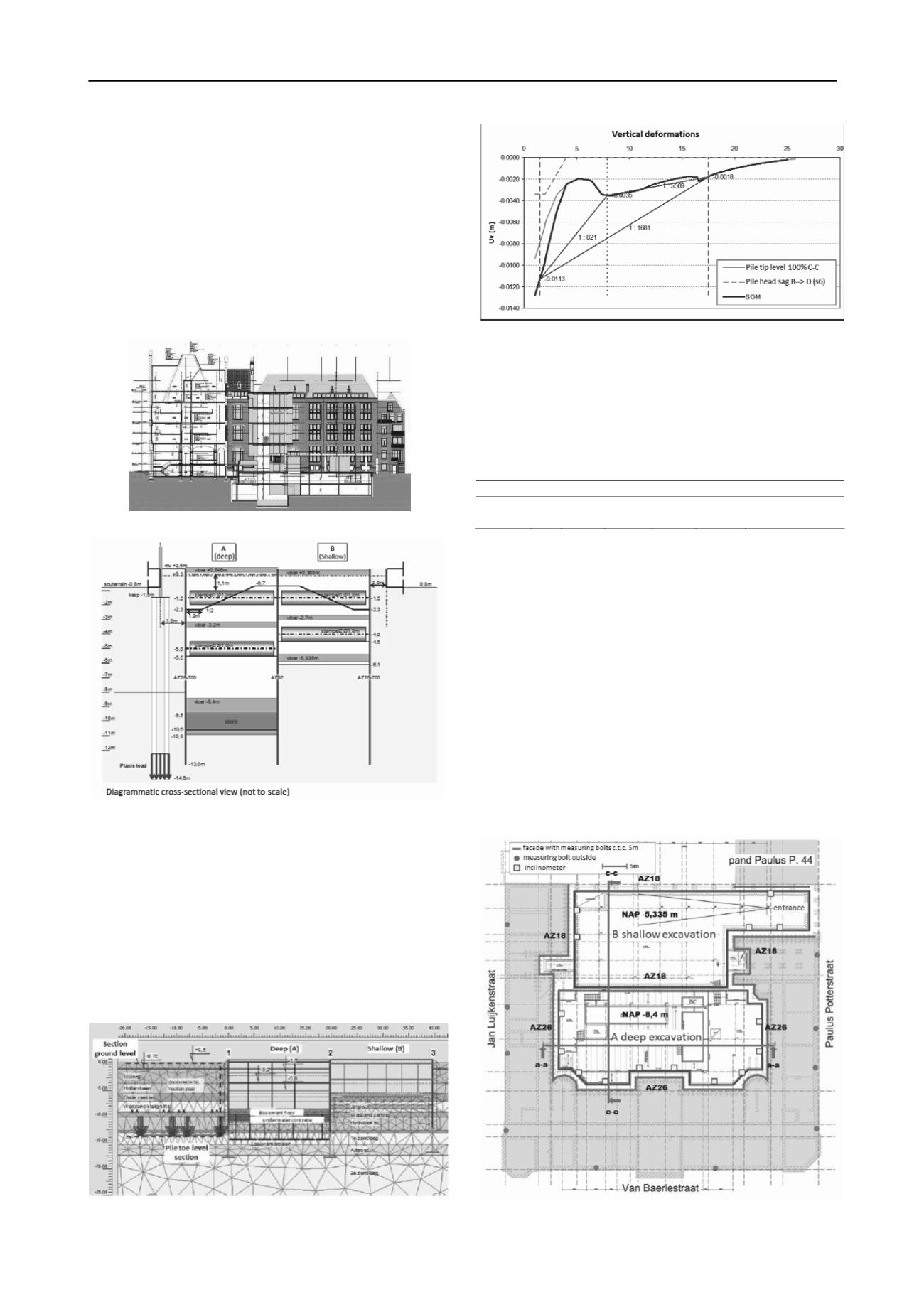
and stresses resulting from this model, the vertical deformations
and inclination of the existing building were determined, see
Figure 6. The sheet piles and struts were designed in such a
iterative way that the damage prediction resulted in an
acceptable damage class(see Table 1).
Figure 5. Plaxis geometry section C-C, shallow excavation NAP -6,1m.
Figure 6. Vertical deformations in building, section C-C.
Because of the proximity of the existing building, full of
marble stairs and exquisite tiles that had to be preserved, all the
applied foundation system were vibration free: the sheet piles
AZ26 were pushed and the Hek-piles were screwed.
Table 1. Results damage prediction sect. C-C (based on BRE regulation
/ Netzel 2010)
u
v
L/H β
Eh
Δ/L
ε
tot
Damage class
m
-
-
%
-
-
-
-0.0113
1:1605 0.066 0.0002 0.00088
Slight (minor
aesthetic damage)
L/H = Ratio depth/height of the building Δ = Vertical deflection
Β = Relative angular distortion
ε
h
= Horizontal strain
ε
tot
= Total building strain
u
v
= vertical displacement
5 MONITORING
5.1
General
Because of the sensitive nature of the existing building and the
high complexity of the execution of the works, an extensive
monitoring program was implemented. Figure 7 shows a
general overviewincluding the position of the levelling point
(bolts) and inclinometers. By measuring the inclination of the
sheet piles, an excellent comparison could be made between
predictions and execution for all stages of the works. The
leveling points were mainly used to verify whether the
inclination indeed resulted in the predicted building
deformation. This is particularly useful because some deviation
from the predictions is not uncommon.
Figure 7. Overview leveling points (bolts) and inclinometers.


