2156
Proceedings of the 18
th
International Conference on Soil Mechanics and Geotechnical Engineering, Paris 2013
Figure 9. Stability charts for the Nerlerk berm.
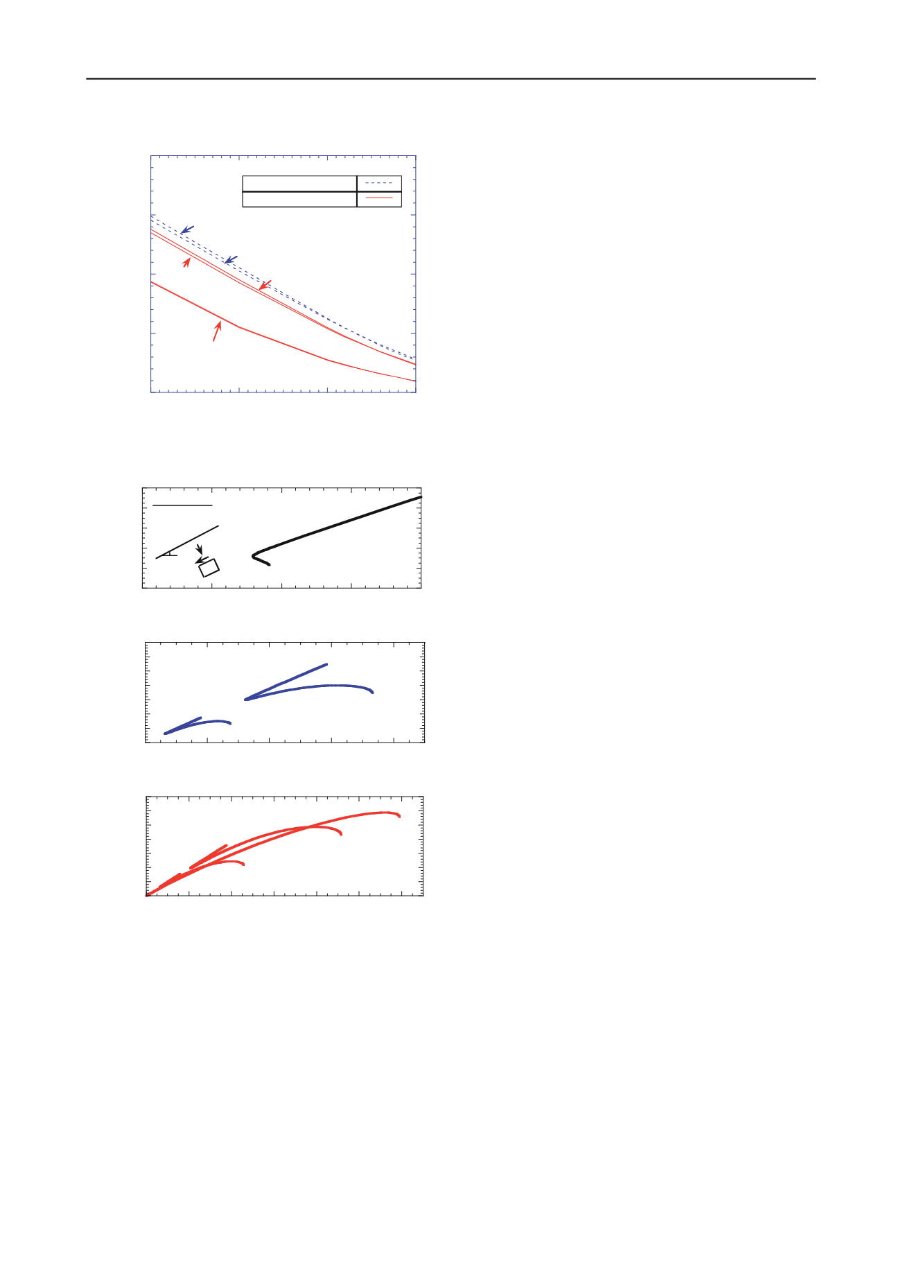
Figure 10. Predictions of undrained response across the Nerlerk berm
section (
α
=13°): a) no potential for liquefaction; b) limited potential for
liquefaction; c) high potential for liquefaction.
4 CONCLUSIONS
This paper has presented a framework for evaluating the
triggering of flow slides in infinite slopes by modeling the
undrained shear behavior using the anisotropic MIT-S1 model.
The selected soil model is able to simulate realistic transitions
in the contractive/dilative response of sands and enables the
prediction of the shear perturbations able to induce instability,
as well as the location of potentially unstable zones within the
soil mass. In this paper, these features have been used to derive
stability charts of triggering perturbations for different
combinations of initial density and stress state.
In practice the model needs to be calibrated for the site
specific properties of the soil, and requires reliable data on in
situ density in order to make predictions of liquefaction
potential. In order to show the capabilities of the proposed
approach, the methodology has been applied to the well-known
case of slope failures in the Nerlerk berm. A general picture of
the distribution of liquefaction susceptibility on the Nerlerk
slope profile has been obtained. The analyses have been based
on the calibration of model input parameters against published
laboratory test results, while empirical correlations for CPT data
have been used to define the initial density conditions prior to
shearing. The results show that there were two zones within the
slope that were vulnerable to flow failure. Although some
sections of the berm were oversteepened, most were deposited
with a slope angle
α
=10°-13°. For these slope angles, the
current analyses show that instability could have been triggered
by the undrained perturbations possibly induced by the rapid
deposition of hydraulic fill. Thus, static liquefaction is likely to
have contributed to the observed failures, confirming earlier
hypotheses by Sladen et al. (1985b).
The analyses presented in this work illustrate a unified
methodology that combines the theory of material stability, the
critical state framework for sands and data from in situ tests. As
a result, the proposed methodology offers a simple, consistent
and complete geomechanical framework for interpreting and
predicting the triggering of flow slides that can be easily applied
to other similar engineering cases.
5 REFERENCES.
Baldi G., Bellotti R., Ghionna V., Jamiolkowski M., Pasqualini E.
(1982). Design parameters for sands from CPT. Proceedings of the
Second European Symposium on Penetration Testing, ESOPT 11,
Amsterdam, Holland, pp. 425-432.
Buscarnera, G., Whittle, A.J. (2012). “Constitutive modeling approach
for evaluating the triggering of flow slides”. Can. Geotech. J. 49(5):
499-511.
Buscarnera, G., Whittle, A.J. (2013). Model prediction of static
liquefaction: the influence of the initial state on potential
instabilities. To appear on J. Geotech. Geoenviron. Eng. ASCE.
Buscarnera G., Dattola G., di Prisco, C. (2011). Controllability,
uniqueness and existence of the incremental response: a
mathematical criterion for elastoplastic constitutive laws. Int. J.
Solids Struct., 48 (13), 1867-1878.
di Prisco C, Matiotti R, Nova R. (1995). Theoretical investigation of the
undrained stability of shallow submerged slopes, Géotechnique ,
45, 479-496.
Hicks M. A., Boughrarou R. (1998). Finite element analysis of the
Nerlerk underwater berm failures. Géotechnique 48, No. 2, 169–
185.
Jefferies M.G., Been K. (1991). Implications for critical state theory
from isotropic compression of sand. Géotechnique 50:44, 419-429.
Hill, R. (1958). A general theory of uniqueness and stability in elastic-
plastic solids. J. of the Mech. and Phys. of Solids 6, pp. 239–249.
Lade P. V. (1993). Initiation of static instability in the submarine
Nerlerk berm. Can. Geotech. J. 30, 895-904.
Pestana J.M., Whittle A.J. (1995). Compression model for cohessionless
soils, Géotechnique, 45 (4), 611-631.
Pestana J.M., Whittle, A.J. (1999). Formulation of a unified constitutive
model for clays and sands, Int. J. Numer. Anal. Meth. Geomech.,
23, 1215-1243.
Poulos, S.J., Castro, G. and France, J. (1985). Liquefaction evaluation
procedure. Journal of the Geotechnical Engineering Division,
ASCE. 111(6): 772-792
Sladen, J. A., D'Hollander, R. D. & Krahn, J. (1985a). The liquefaction
of sands, a collapse surface approach. Can. Geotech. J. 22, 564-578.
Sladen, J. A., D'Hollander, R. D., Krahn, J. & Mitchell D. E. (1985b).
Back analysis of the Nerlerk berm Liquefaction slides. Can.
Geotech. J. 22, 579-588.
Terzaghi K. (1957). Varieties of submarine slope failures. NGI
Publication N. 25, 1-16.
0
0,05
0,1
0,15
0,2
0
5
10
15
z=3.0m
z=8.0m
z=13.0m and z=15.0m
z=5.0m
z=10.0m
Slope Inclination,
α
[°]
Partial Liquefaction
Complete Liquefaction
MIT-S1 - Nerlerk 12%
Perturbation Shear Stress Ratio,
∆τ
/
γ
'z
γ
'z - vertical overburden pressure
0
2
4
6
8
10
0
5
10
15
20
z=1m
Normal Effective Stress,
σ
'
ξ
[kPa]
MIT-S1
Nerlerk 12%
α
σ
'
ξ
τ
ξη
Shear Stress,
τ
ξη
[kPa]
0
5
10
15
20
25
30
35
0
20
40
60
80
z=3m
z=8m
Normal Effective Stress,
σ
'
ξ
[kPa]
Shear Stress,
τ
ξη
[kPa]
0
5
10
15
20
25
30
35
0
20
40
60
80
100 120
z=5m
z=10m
z=13m
Normal Effective Stress,
σ
'
ξ
[kPa]
Shear Stress,
τ
ξη
[kPa]
a)
b)
c)


