1654
Proceedings of the 18
th
International Conference on Soil Mechanics and Geotechnical Engineering, Paris 2013
Proceedings of the 18
th
International Conference on Soil Mechanics and Geotechnical Engineering, Paris 2013
4 TRIAL CALCULATION OF RESIDUAL
DISPLACEMENT OF RETAINING WALL
4.1
6B
Damaged railway retaining wall during 1995 Hyogo-
ken nambu earthquake
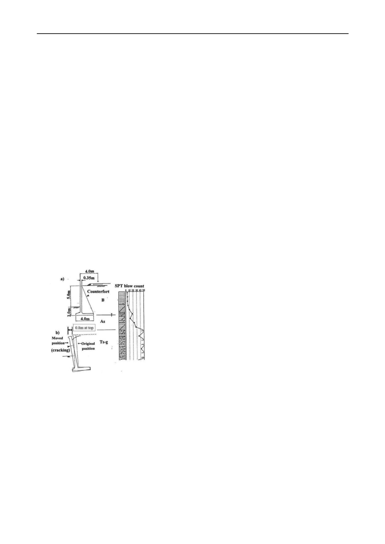
The railway retaining wall selected for the trial calculation is a
cantilever type retaining wall in Ishiya River District, which
suffered critical failure during the 1995 Hyogo-ken nambu
earthquake (Figure 8). The retaining wall is 7m in height, and
has a spread foundation. According to detailed investigations
after the earthquake, the major displacement mode of this
retaining wall was overturning, and an 800mm horizontal
displacement was observed at the top end of the retaining wall.
A number of subsoil parameters were obtained such as the N
value from standard penetration tests performed after the
earthquake. In addition, backfill soil material was determined
based on field density tests and drained tri-axial tests on
reconstituted samples.
Recorded seismic ground motion, such as N-S components
from Kobe Marine Meteorological Observation Station, was
employed in the trial calculation, considering the orientation of
the retaining wall. The residual horizontal displacement at the
top end of the retaining wall, which was calculated from the
Newmark method (overturning mode), was 570mm. Even
though the amount was slightly less than the actual value
(800mm), the result was closer to the actual value than the
calculated values obtained with the current seismic standard
based on the energy constant law (353mm). This is because the
energy constant law only considers maximum acceleration, and
is unable to consider seismic ground motion characteristics such
as duration and number of seismic motions.
Figure 8 Damaged railway retaining wall after the 1995 Hyogoken-
Nanbu earthquake (Tatsuoka et al. 1998)
4.2
7B
Shaking table test results of gravity type retaining wall
model
The time history of the horizontal displacement and rotational
angle obtained from the Newmark method are shown in Figure
4 and compared to their measured values. Cases of coupled
displacement mode (sliding and overturning modes) occurred
during shaking table tests, however trial calculations were made
for one case in which the failure mode combination (sliding
mode and overturning mode) was considered and one case in
which the failure mode combination was not considered.
Where coupled displacement mode was not considered, the
Newmark method underestimated the sliding mode (horizontal
displacement) and overestimated the overturning mode
(rotational angle). In the sliding mode, the horizontal force and
moment actually act simultaneously, resulting in a decrease of
the maximum horizontal bearing capacity (R
hd
’
in Figure 7) as
shown in Figure 5. That is why the horizontal displacement is
underestimated. On the other hand, in the overturning mode,
the overestimation of the rotational angle compared to the
experimental value is mainly due to the correction coefficient
for inclined loads (Iγ) which is used to determine the maximum
resistant moment (M
md
’
in Figure 7). This correction coefficient
was obtained through experiments performed by Meyerhof
(1953), however, there may be an applicable limit in the case
where the ratio of horizontal force to vertical force is large due
to the effect of inertial force and seismic earth pressure such as
is the case with retaining walls. The above result shows the
limit to dealing with sliding and overturning modes
independently in cases where the retaining wall is suffering
from the effects of the failure mode combination.
Notwithstanding, when considering the coupled displacement
modes sliding and overturning, it is clear that the horizontal
displacement is consistent with the experimental value (Figure
4). The rotational angle value is also generally reproduced in
the experiment though still overestimated. This is because
slight recovery of rotational angle (elastic behavior, Figure 5a)
was ignored in the Newmark method when the external forces
were applied in the backward direction (passive direction), and
the maximum resistant moment (M
md
’
) was still underestimated
which corresponds to the residual strength of the bearing
capacity.
5 CONCLUSION
A series of model shaking tests were carried out on
conventional retaining wall, and its dynamic response
characteristics was evaluated. The dynamic response of the
retaining wall was largely affected by the seismic ground
motion characteristics (duration and number of seismic
motions), whereas response acceleration amplification was
insignificant.
Based on these test results, a proposal was made for retaining
wall seismic design method based on the Newmark method.
The yield surface of the bearing capacity was used in the
proposed method in order to consider the failure mode
combination (sliding and overturning). The seismic design
method proposed in this study was confirmed as being generally
able to reproduce experiment results and cases of past damage.
The proposed seismic design methods have been employed in
the new railway design standard for retaining structures in
Japan, which was revised into a performance-based design in
2012.
6 REFERENCES
Railway Technical Research Institute., “Railway structure design standard for
foundations and soil retaining structures (SI unit version)”, Maruzen, 2000
.
(in Japanese)
Railway Technical Research Institute., “Ea
rthquake design standard for railway
structure”, Maruzen, 1999
. (in Japanese).
Railway Technical Research Institute., “Railway structure design standard for
earth structure
”, Maruzen, 200
7. (in Japanese)
Railway Technical Research Institute., “Railway stru
cture design standard for soil
retaining structures”, Maruzen, 20
12. (in Japanese)
Meyerhof, G. G., “The Bearing Capacity of Foundation under Eccentric and
Inclined Loads”, Proc., 3rd Int. Conf. on Soil Mechanics and Foundation
Engineering, Switzerland, pp.440-445, 1953.
Nishioka, H., Hino.A., Koda, M. and Murono. Y.,
“
Seismic design procedure of
conventinal type bridge abutment and an ezample of ite performance
verification
”
, RTRI REPORT.2012. (in Japanese)
Newmark, N. M.: Effects of earthquake on the dams and embankments,
Geotechnique, Vol.15, No2.pp.139-159, 1965.
Tatsuoka, F., Koseki, J., Tateyama, M., Munaf., Y., and Horii, K., “Seismic
stability against high seismic loads of geosynthetic-reinforced soil retaining
structures”, Keynote Lecture,
Proc., 6th Int. Conf. on Geosynthetics
, Atlanta,
1998.
Watanabe, K., Munaf, Y., Koseki, J., Tateyama, M. and Kojima, K.: Behaviors of
several types of model retaining walls subjected to irregular excitation, Soils
and Foundations, Vol.43, No.5, pp.13-27, 2003.


