 
          1653
        
        
          Technical Committee 203 /


            Comité technique 203


            Proceedings of the 18


            th


            International Conference on Soil Mechanics and Geotechnical Engineering, Paris 2013


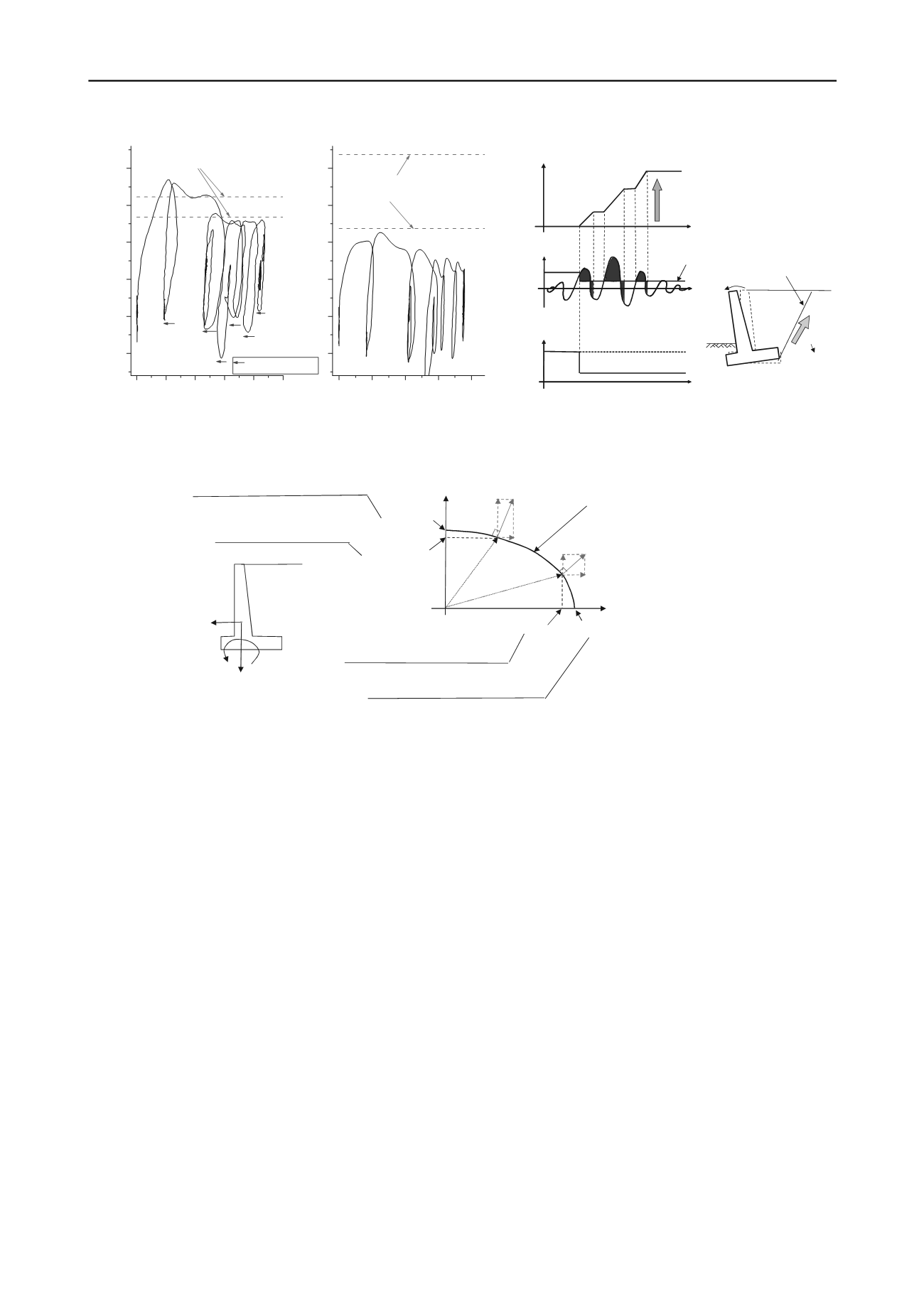
          force reaches the maximum value. This maximum value has
        
        
          been identified as being generally consistent with the maximum
        
        
          resistance moment (M
        
        
          md
        
        
          ) and the maximum horizontal bearing
        
        
          capacity (R
        
        
          hd
        
        
          ) of a retaining wall as shown in Figure 5 (see
        
        
          below for detail). On the other hand, recovery of displacement
        
        
          (elastic behavior) was small when the external forces were
        
        
          applied in the backward direction (passive direction). It can be
        
        
          said that the displacement increment of the retaining wall to the
        
        
          active direction is largely affected by seismic ground motion
        
        
          characteristics (duration and number of seismic motions).
        
        
          3 A NEW METHOD TO EVALUATE THE RESIDUAL
        
        
          DISPLACEMENT OF RETAINING STRUCTURES.


            3.1


          4B


            Retaining wall


          Based on the test results, a seismic design method using the
        
        
          Newmark method (Newmark, 1965) was proposed for the
        
        
          retaining wall (Figure 6).
        
        
          The Newmark method has various advantages in that (1) the
        
        
          theory is very simple and has very few analytical parameters
        
        
          while still providing an adequate result; (2) seismic ground
        
        
          motion characteristics can be directly considered, and (3) the
        
        
          strength characteristics and strain softening behavior of the
        
        
          backfill soil can be taken into account.
        
        
          According to experience gained in the wake of past disasters
        
        
          and model experiment results, overturning modes (rotational
        
        
          mode) are common in the seismic response of retaining wall
        
        
          foundations. Therefore, the Newmark method is indicated as
        
        
          the method for calculating the response rotational angle of a
        
        
          retaining wall in the new design standard. However since a
        
        
          considerable eccentricity/inclined load at the base footing is
        
        
          often caused by seismic earth pressure, this effect should be
        
        
          considered when calculating the maximum resistance moment
        
        
          (M
        
        
          md
        
        
          ’
        
        
          in Figure 7) of the foundation.
        
        
          Furthermore, an
        
        
          overturning mode does not necessarily occur independently but
        
        
          can also be simultaneously accompanied by a sliding mode
        
        
          when a spread foundation-type retaining wall has a low center
        
        
          of gravity or when the passive resistance force at the front side
        
        
          of base footing is small.
        
        
          However, such failure mode
        
        
          combinations cannot be taken into direct consideration since the
        
        
          Newmark method uses a different motion equation for sliding
        
        
          modes and overturning modes. Therefore, the combination of a
        
        
          sliding mode and an overturning mode is determined if the
        
        
          horizontal external force exceeds an horizontal stability level
        
        
          when the response of the retaining wall reaches the maximum.
        
        
          The displacement caused by the major failure mode is
        
        
          calculated by the Newmark method and the displacement
        
        
          caused by the minor failure mode is calculated from the yield
        
        
          surface of the bearing capacity considering the associated flow
        
        
          rule (Figure 7).


            3.2


          5B


            Bridge abutment


          Although the details of a study for bridge abutments have
        
        
          been omitted due to space limitations in this paper, the effect of
        
        
          inertial force and dynamic amplification was significant for
        
        
          bridge abutments (Nishioka et al, 2011). This is because the
        
        
          bridge abutment sustains the heavy bridge girder at the top.
        
        
          This dynamic response characteristic is similar to that of a
        
        
          bridge pier. In view of the above, a seismic design method was
        
        
          proposed, which models the bridge abutment as a single-degree-
        
        
          of-freedom system. This design method is almost similar to
        
        
          bridge pier, however, seismic earth pressure acting on the
        
        
          backface of bridge abutment is also considered.
        
        
          0.00 0.01 0.02 0.03 0.04 0.05
        
        
          0.00
        
        
          0.05
        
        
          0.10
        
        
          0.15
        
        
          0.20
        
        
          0.25
        
        
          of rotational angle
        
        
          :slight elastic recovery
        
        
          overturning mode
        
        
          sliding and
        
        
          overturing mode
        
        
          Calculated maximum
        
        
          resistance moment(M
        
        
          md
        
        
          )
        
        
          Overturning moment(kN m/m)
        
        
          Response rotational angle(rad)
        
        
          0 5 10 15 20
        
        
          0.0
        
        
          0.5
        
        
          1.0
        
        
          1.5
        
        
          2.0
        
        
          2.5
        
        
          a)
        
        
          b)
        
        
          overturning mode
        
        
          sliding and
        
        
          sliding mode
        
        
          maximum horizontal
        
        
          bearing capacity(R
        
        
          hd
        
        
          )
        
        
          Horizontal external force(kN/m)
        
        
          Horizontal displacment
        
        
          at the bottom(mm)
        
        
          Figure 5 Relationship between overturning moment (external
        
        
          Figure 6 Newmark method for retaining wall (overturning mode)
        
        
          force) and response rotational angle (horizontal displacement)


            H


            M


          H
        
        
          M
        
        
          V


            M


            md


          ′


            H


            max


            H


            max


          ′


            M


            md


          Maximum resistance moment
        
        
          (overturning mode)
        
        
          • •


            =R


            hb


          • •
        
        
          • •


            =R


            hb


          ′
        
        
          )
        
        
          Yield surface of the
        
        
          bearing capacity
        
        
          <External force acting on foundation>
        
        
          Bδθ
        
        
          Displacement
        
        
          increment vector
        
        
          δh
        
        
          δh
        
        
          Bδθ
        
        
          δh
        
        
          :
        
        
          Horizontal displacement increment
        
        
          Bδθ
        
        
          :
        
        
          Rotational angle increment
        
        
          (B
        
        
          :
        
        
          footing width)
        
        
          Displacement
        
        
          increment vector
        
        
          Maximum resistance moment
        
        
          (under the combination of sliding
        
        
          and overturning mode)
        
        
          Maximum horizontal bearing capacity
        
        
          (sliding mode)
        
        
          Maximum horizontal bearing capacity
        
        
          (under the combination of sliding and
        
        
          overturning mode)
        
        
          Figure 7 Yield surface of bearing capacity and the associated flow rule
        
        
          Moment, M
        
        
          M
        
        
          md
        
        
          (threshold)
        
        
          φ
        
        
          peak
        
        
          φ
        
        
          res
        
        
          Responserotational
        
        
          angle(rad)
        
        
          Time
        
        
          Accumulation of
        
        
          rotational angle
        
        
          Mobilized internal
        
        
          friction angle
        
        
          Peak strength
        
        
          Residualstrength
        
        
          Failureplane
        
        
          φ
        
        
          peak
        
        
          φ
        
        
          res
        
        
          Overturning
        
        
          Time
        
        
          Time