616
Proceedings of the 18
th
International Conference on Soil Mechanics and Geotechnical Engineering, Paris 2013
Proceedings of the 18
th
International Conference on Soil Mechanics and Geotechnical Engineering, Paris 2013
2 GEOLOGICAL CONDITIONS
Geological conditions of the construction site can be
described as unfavorable for civil engineering and especially for
high-rise buildings. Weak water-saturated soils lies to the depth
of 30 ... 35 m. Underneath these soils is a layer of moraine
deposits of small thickness. From a depth of 45 m liesVendian
clay. Rock, commonly used as a bearing stratum for high-rise
buildings are located at depths of over 200 m. Considering the
aforementioned facts Vendian clay was selected as the bearing
layer for the Okhta tower pile foundation. Vendian clay is
relatively strong soil and classified as hard clay and weak rock
at the same time. Despite the relatively high strength properties
Vendian clay exhibits long-term development of deformations
in time under load. It should be noted that engineering
properties of these soils in Saint-Petersburg is mostly unstudied.
3 TESTING SETUP
The test program was design in such a way as to achieve the
following goals:Determination of the bearing capacity of
barrette and it’s individual fragments;Determination of load-
settlement
characteristics
for
"top-down"
loading
scheme;evaluation of the Young modulus for the underlying the
barrette base;Evaluation of interface strength on the shaft of the
barrette.
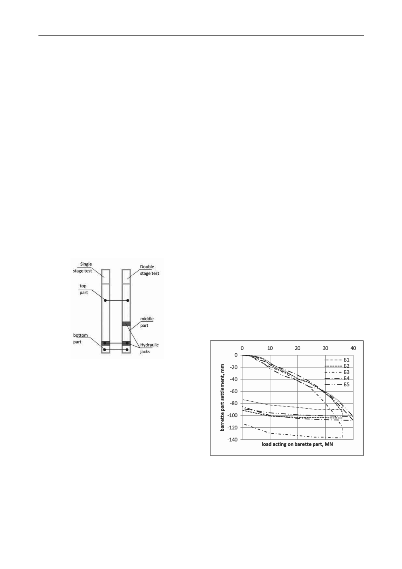
Three of the five tested group barrettes were equipped with
loading device installed in two levels, two single piles in one
level. Single-level and two-level testing scheme and barrette
part nameingare shown in Fig. 2
Figure2. Scheme of barrete parts namings
Barrettes with one level jacks were tested in one phase, the
pile with two levels - in two stages. In the first stage the lower
part of the pile is loaded with the lower level of the jack. In the
second stage the upper jack level creates load on the middle part
of barrette. During a first stage of testing upper level jacks are
closed and load transfer through them is not different from a
solid barrette section. During loading of the upper level, the
hydraulic system of lower jacks is open into atmosphere,
making them closing or opening freely. During the testing of the
upper level when the lower level is open and jacks are retracted,
the entire load of the upper level of loading is transmitted to the
shaft of the barrette middle fragment. As the criteria for test
advancement standard RF deformation stabilization criteria 0.1
mm/h was used. It is 2.5 times more rigorous then the standard
European 0.25 mm/h. Results comparison with two different
stabilization criteria showed, that application of the criterion of
0.25 mm/h underestimates the magnitude of barrete base
displacement by 30%. Choice of stabilization criteria is
especially important when the testing jack located near the
barrette base in clay soils, as in this case, due to soil
consolidation deformation process is much slower.
4 TEST RESULTS
4.1 Test of the lower parts of barrettes B1...B5.
The value of the load reached during first stage of testing
was 40MN and 48 MN for second stage.
Bearing capacity of the lower parts of the test group barrette
was 90% of the bearing capacity for a single barretes test, due to
the group effect.
Load-settlement characteristics for barrettes B1…B5 shown
on Figure 3 and shows that settlement of Barrette B2, located
between Barrette B1 and B3 is 15% more than that of Barrette
B1. This effect is referred to well-known concepts of group
effect in pile groups. Pile settlement in the group always
exceeds the settlement of single pile, and the settlement of
central pile is highest. With the growth of the number of piles in
the group this effect expected to increase. By means of
mathematical modeling of group testing and achieving the same
group effect, which was observed in the trial, one can confirm
the accuracy of the model input parameters, and to validate its
use for the calculation of the entire foundation.
The elastic component of the Barrette B1 ... B5 base
settlement is 13 ... 20%, and the residual inelastic component
reaches 79 ... 87.6% (Fig. 3), i.e. much of the ground under the
base of Barrette undergone plastic deformation.
In the analysis of Fig. 3 it may be seen that load-settlement
characteristics can be divided into several stages. In the first
phase, with a load values up to 5MN, load held by the shaft
friction on the surface of Barrette part, and movement up to 1
mm recorded. At the 2nd stage of loading barrete part is moved
and load being transferred to barrete base. Soil underneath the
barrete disturbed by drilling began to compact under load.
Settlement of barrete base increases linearly with load until
20…40 MN load value is reached. As the barrette part
movement increases, shaft frictions on its side reaches a
maximum value and remain constant to the rest of stage 1. Due
to this effect further increment of load transferred directly to the
barrette base. The final stage is characterized by an increase of
settlement increment per unit increment of load, indicating that
the transition of the ground under the base of barrette to the
plastic state.
Figure 3. Stage 1 test results.
In order to clarify the shaft bearing capacity for bottom part
of Barrette B4, the loading increments in the first stages of the
load testing has been reduced from 5MN to 2.5 MN, which led
to an increase in the number of stages in the load range of up to
20 MN from 4 to 8 . An interesting finding was the fact that,
regardless of the number of stages loading time spent on testing
barrette B4 and B5, was similar and was 277 and 259 hours,
respectively.
Concluding the analysis of bottom level testing one can
mention high repeatability of results, which indicates the


