3498
Proceedings of the 18
th
International Conference on Soil Mechanics and Geotechnical Engineering, Paris 2013
displacement controlled cyclic tests was designed (Vieira et al.
2013).
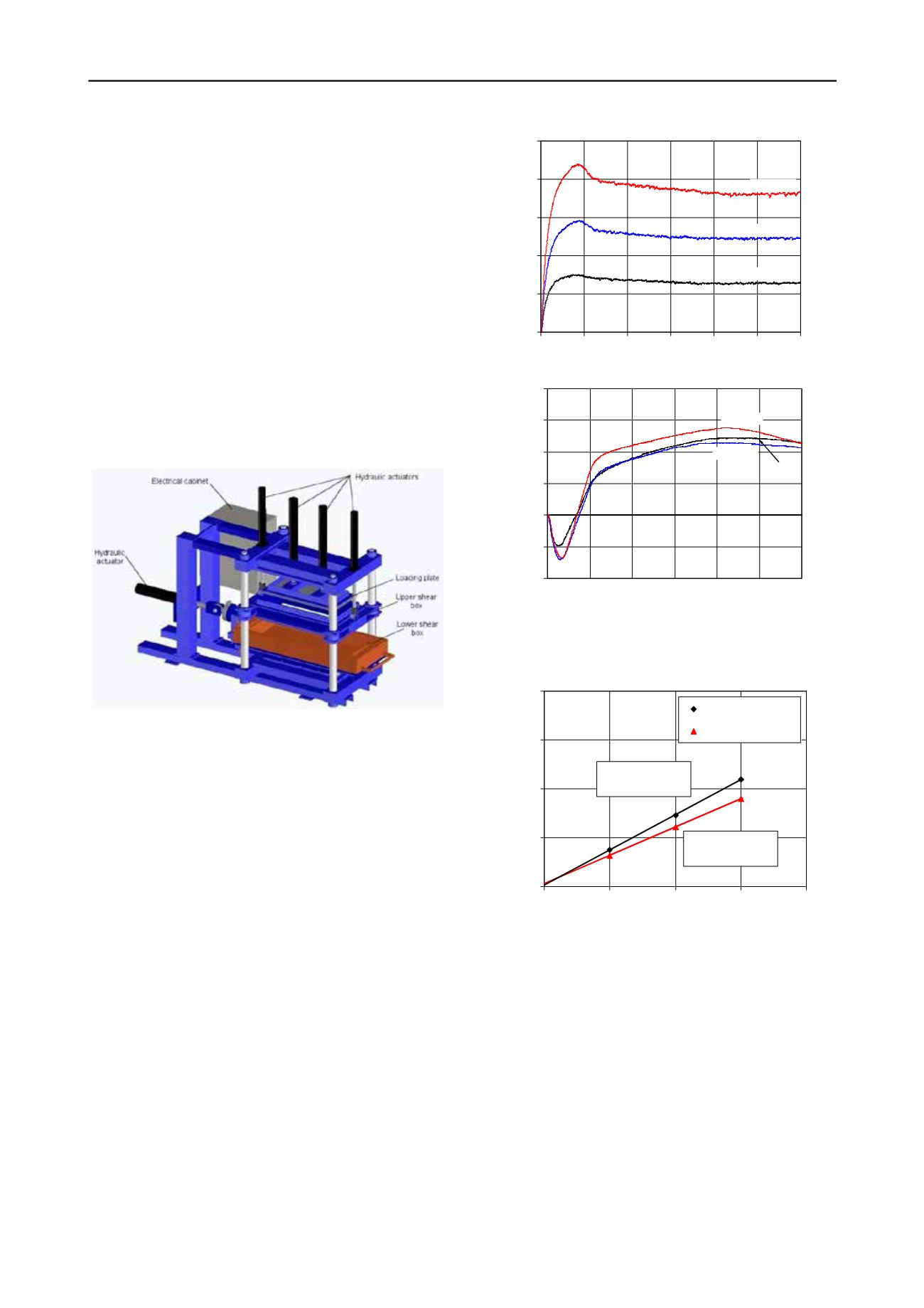
The developed large scale direct shear device is based on a
hydraulic actuation with closed loop command computer
control. The apparatus consists of the shear box, a support
structure, five hydraulic actuators and respective fluid power
unit, an electrical cabinet, internal and external transducers and
a computer. Figure 2 shows a schematic view of the apparatus.
The shear box comprises an upper box, fixed in the
horizontal directions, with dimensions of 300 mm × 600 mm in
plant and 150 mm height, and a lower box, with dimensions of
340 mm × 800 mm in plan and 100 mm height, rigidly fixed to
a mobile platform running on low friction linear guides. More
details can be found in Vieira
et al.
(2013).
The direct shear tests were performed with a rigid base
placed on the lower box (constant contact area tests). The sand
was placed inside the upper shear box, at its air-dried water
content, with relative density (I
D
) of 70%. It was compacted in
two thick layers with 25 mm height to the target unit weight.
The tests were conducted with a constant displacement rate of
1 mm/min at normal stresses of 50, 100 and 150 kPa.
Figure 2. Schematic view of the direct shear test apparatus.
3.2
Direct shear tests results
The evolution of the shear stress and the vertical displacement
of the rigid plate centre, as function of the shear displacement,
for the sand SP49/geocomposite GC100 interface is shown in
Figure 3.
The shear stress-shear displacement curves (Figure 3a) show
a well-defined peak shear strength, which was recorded for
shear displacements that increased with the confining pressure.
As expected, initially, the sand exhibited a contraction followed
by a dilating phase (Figure 3b). After reaching the peak of the
interface shear strength, the vertical displacement progress
during shear for confining pressure of 100 kPa is similar to the
one observed for the lower stress (50 kPa).
Figure 4 presents the peak and the large displacement shear
strengths for the three values of the confining pressure (50 kPa;
100 kPa, 150 kPa), as well as the corresponding linear best fits.
Following Coulomb failure criterion, the SP49/GC100 interface
presented an apparent adhesion c
a,p
= 1.4 kPa and a peak friction
angle
δ
p
= 35.8º. The large displacement strength can be defined
by an apparent adhesion c
a,cv
= 3.0 kPa and friction angle
δ
cv
= 30.2º. The failure envelopes show an apparent adhesion
for the sand/geotextile interface due to the nonlinearity of the
relationship between the shear strength and the normal stress at
lower confining stresses. Even so, the values for this parameter
can be considered without great significance.
Notice that, the apparent adhesion has also been reported by
other authors for sand/geosynthetic interfaces (Ling
et al.
2002;
Liu
et al.
2009).
0
25
50
75
100
125
0.0 10.0 20.0 30.0 40.0 50.0 60.0
Shear displacement (mm)
Shear stress (kPa)
50 kPa
150 kPa
100 kPa
(a)
-0.2
-0.1
0
0.1
0.2
0.3
0.4
0.0 10.0 20.0 30.0 40.0 50.0 60.0
Shear displacement (mm)
Vertical displacement (mm)
50 kPa
100 kPa
150 kPa
(b)
Figure 3. Direct shear tests results for different normal stresses (50, 100
and 150 kPa): (a) shear stress-shear displacement; (b) vertical
displacement-shear displacement.
τ
= 0.5814
σ
+ 2.9838
R
2
= 0.9999
τ
= 0.7208
σ
+ 1.4161
R
2
= 0.9998
0
50
100
150
200
0
50
100
150
200
Normal stress (kPa)
Shear stress (kPa)
Peak
Large displacement
Figure 4. Peak and large displacement shear strengths as a function of
the applied normal stress.
4 CHARACTERIZATION OF GEOSYNTHETIC
REINFORCED SAND BY SIMPLE SHEAR TESTS
In this work a simple shear device Norwegian Geotechnical
Institute type, model Geonor h-12 was used. It is a linear simple
shear apparatus, which differs from the conventional direct
shear devices since tilting elements delimit the vertical
boundaries of the specimens, allowing a more uniform
deformation of the soil and the rotation of principal stresses.
Besides the failure planes are not imposed.
The specimens are cylindrical, with a height of 16 mm and a
diameter of about 80 mm, enclosed in a wire-reinforced
membrane. In the tests of reinforced sand the thickness of
geosynthetic was deducted from the height of specimen to
determine the amount of sand corresponding to the desired


