3458
Proceedings of the 18
th
International Conference on Soil Mechanics and Geotechnical Engineering, Paris 2013
3 DETAILS OF THE PARAMETRIC STUDY
Once the 3D finite element model (Composite Soil Model) to be
used for the analysis of rigid footings resting on rammed
aggregate piers was calibrated using the results of full-scale
load tests as presented in the previous chapter, the next step is to
carry out a parametric study using this finite element model to
investigate the effect of both geometric parameters (area ratio of
rammed aggregate piers, foundation load, width of foundation,
rammed aggregate pier length) and material parameters
(strength of foundation material, modulus of elasticity value of
rammed aggregate piers) on the settlement improvement factor.
Three different footing sizes (2.4mx2.4m, 3.6mx3.6m and
4.8mx4.8m) were used for the parametric study. The thickness
of the compressible clay layer under these footings was varied
as Lclay = 5m, 10m and 15m for each different footing size.
Four different area ratios (AR= 0.087, 0.136, 0.230 and 0.349)
were used for the rammed aggregate pier groups under each
different footing and compressible layer combination.
Foundation pressures, q, were selected as q=25-50-75-100-125-
150 kPa. Schematic representation of these parameters can be
seen in Figure 11. The strength and deformation modulus values
of the compressible clay layer were varied as shown at Table 2.
The deformation modulus value of the rammed aggregate piers
were selected as E
column
= 36 MPa and 72MPa.
Table 2. Strength and deformation properties of the compressible clay
layer used in the parametric study.
(kN/m
3
)
c
(kN/m
2
)
(°)
E
clay
(kN/m
2
)
18
20
0
0.35
4500
18
25
0
0.35
5625
18
30
0
0.35
6750
18
40
0
0.35
9000
18
60
0
0.35
13500
Figure 11 Schematic representation of composite soil model
For each case, first the untreated case is analyzed by
modelling the uniformly loaded rigid footing on compressible
clay using PLAXIS 3D Foundation. Untreated soil settlements
were obtained by this way. Next, the rigid footings resting on
rammed aggregate piers were modeled by PLAXIS 3D
Foundation using the Composite Soil Block approach that was
explained in detail in the previous section. Once the settlement
values for the footings resting on rammed aggregate pier groups
are calculated using this method, settlement improvement
factors are calculated as:
IF = s
untreated
/ s
treated
(1)
where:
IF = settlement improvement factor
s
untreated
= settlement of rigid footing resting on untreated soil.
s
treated
= settlement of rigid footing resting on soil treated
with rammed aggregate pier group.
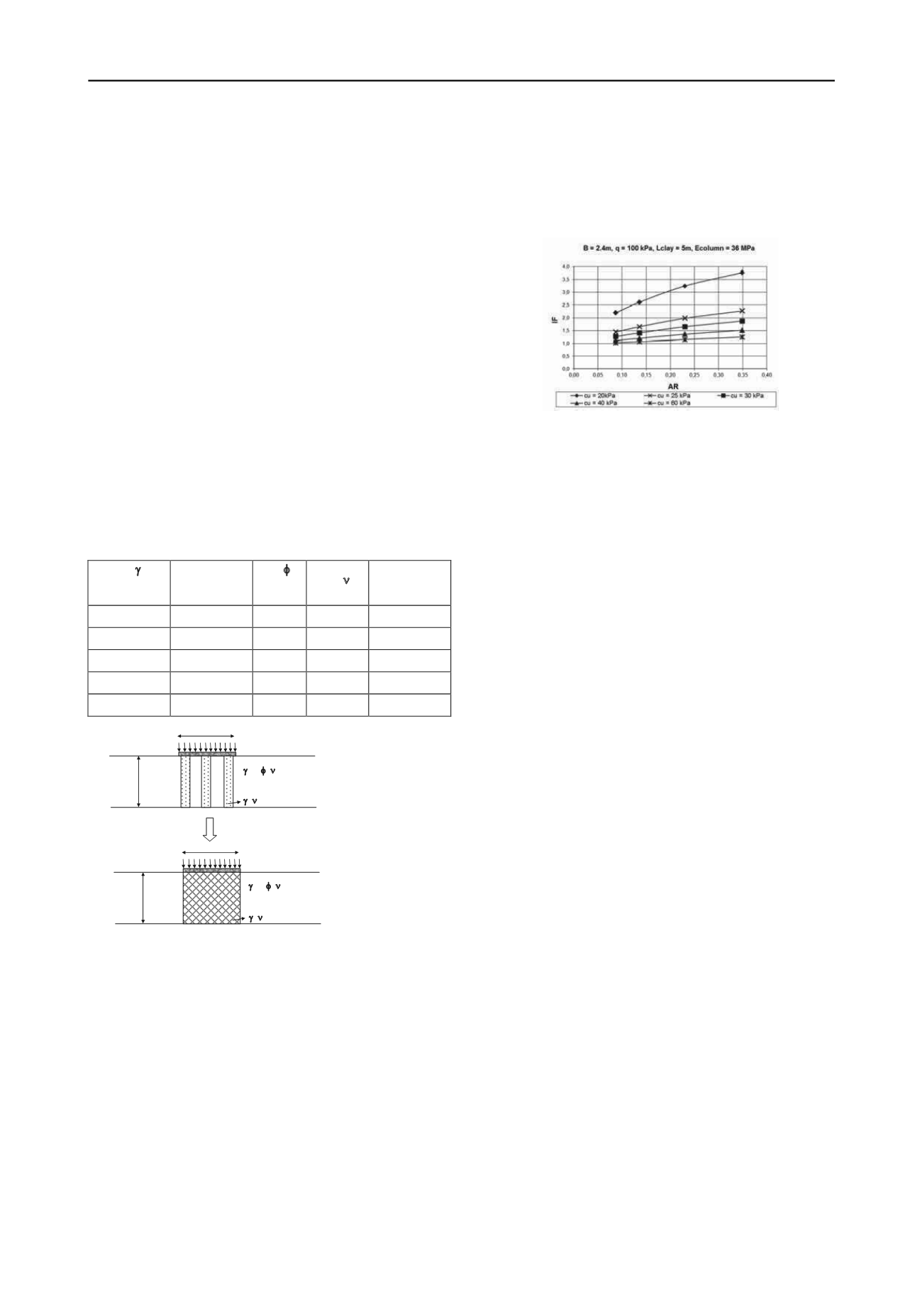
The results of the parametric study detailed in this section
are presented as design charts at Kuruoglu (2008). A sample
design chart is shown in Figure 12. The design charts can be
used to decide on the necessary area ratio of rammed aggregate
piers for a target settlement improvement ratio for footings on
compressible soils resting on rammed aggregate pier groups.
Figure 12. Settlement improvement factor (IF) vs. area ratio (AR) charts
for a rigid square footing (B=2.4m) with a foundation pressure of
q=100 kPa resting on end bearing rammed aggregate piers
(L=5m, E=36 MPa)
As a result of the parametric study, it was found that, the
settlement improvement factor increases as the area ratio, pier
modulus and footing pressure increase. On the other hand, the
settlement improvement factor is observed to decrease as the
undrained shear strength and thickness of compressible clay and
footing size increase.
4 CONCLUSIONS
A simplified 3D finite element model (Composite Soil Model)
calibrated with the results of full scale load tests was developed,
which shows that 3D models for estimating settlement
improvement factor for foundations resting on rammed
aggregate piers can be much simplified by modeling the area
under the footing as a composite soil block with equivalent
linear elastic soil properties, taking the stiffness increase around
the piers during the installation process into account. It is to be
mentioned that the model should be used cautiously for floating
pier groups with pier lengths less than 1.5B (B = width of the
footing), especially at high surface pressure levels , i.e. q / qult
> 0.5, where qult = ultimate bearing capacity of the native soil.
Using this simplified model, design charts for settlement
improvement factors of square footings of different sizes
(B = 2.4m to 4.8m) resting on aggregate pier groups of different
area ratios (AR = 0.087 to 0.349), pier moduli
(Ecolumn = 36MPa to 72MPa), and with various compressible
clay layer strengths (cu = 20kPa to 60kPa) and thicknesses
(L = 5m to 15m) were prepared.
As a result of the parametric study, it was found that, the
settlement improvement factor increases as the area ratio, pier
modulus and footing pressure increase. On the other hand, the
settlement improvement factor is observed to decrease as the
undrained shear strength and thickness of compressible clay and
footing size increase.
5 REFERENCES
Handy R.L. 2001. Does lateral stress really influence settlement.
Journal of Geotechnical and Geoenvironmental Engineering
127
(7), 623-626.
Kuruoglu O. 2008. A new approach to estimate settlements under
footings on rammed aggregate pier groups.
Thesis presented to the
Middle East Technical University in partial fulfillment of the
requirements for the degree of Doctor of Philosophy
. Ankara,
Turkey.
Özkeskin A. 2004. Settlement reduction and stress concentration factors
in rammed aggregate piers determined from full scale load tests.
Thesis presented to the Middle East Technical University in partial
fulfillment of the requirements for the degree of Doctor of
Philosophy
. Ankara, Turkey.
L
clay
L
clay
Rigid Base
Rigid Base
B x L
B x L
q
q
Clay layer
, c,
,
, E
clay
Clay layer (Mohr-Coulomb Model)
, c,
,
, E
clay
Rammed Aggregate Pier
,
, E
column
, AR
Composite Soil Block (Linear Elastic Model)
,
, E
composite


