3460
Proceedings of the 18
th
International Conference on Soil Mechanics and Geotechnical Engineering, Paris 2013
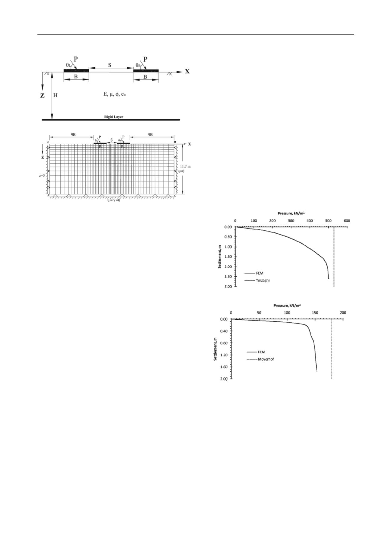
Figure 1. Definition of problem.
Figure 2. Discretized finite element domain and boundary conditions.
3 ANALYSIS
3.1
Modeling
The length of the strip footing is long enough compared to its
width so the problem falls under plane strain condition.
Henceforth two dimensional finite element analysis is carried
out using the commercially available finite element software,
ABAQUS 6.10. The soil is considered as elasto-plastic material
obeying the Mohr Coulomb failure, where the parameter
required for Mohr Coulomb plasticity model are prescribed in
the previous section. The concrete footings are assumed to be
linear elastic with a Young’s modulus of 23.5e+6 kN/m
2
and a
Poisson ratio of 0.2. The finite element mesh is generated with
the use of CPE4R, a 4-node bilinear plane strain quadrilateral
elements. The footings are placed on the surface of soil and
have perfect contact with the soil. The nodes between footing
and soil are tied using the tie constraints and no slip is allowed
at the interface of footing bottom and soil. For the analysis of
geotechnical problems, the initial state of stress is important and
henceforth prior to application of external footing load the soil
is analysed for initial state of stress with the use of geostatic
step wherein the gravity load is applied. The static analysis may
terminate when a few soil elements near the edge of the
footings are distorted excessively which may happen at the
ultimate state of failure. Hence the analysis is performed with
dynamic implicit step where in the external footing load is
applied very slowly to avoid the exciting the finite element
model. The whole failure domain is considered in the present
analysis to take care of both symmetrical and asymmetrical
problems.
3.2
Finite element domain, mesh and boundaries
Figure 2, shows two (left and right) footings, size of failure
domain, finite element mesh and boundary conditions. 4-noded
bilinear rectangular plane strain elements are used to discretized
the soil domain and suitable boundary conditions are assigned at
the far end boundaries of the domain (Potts and Zdravkovic
1999). The bottom end BC is associated with fixed supports (no
displacements are allowed) and side boundaries (AB and DC)
are only fixed in horizontal direction. It is noted that the mesh is
finer in the vicinity of the footings to take care of stress
concentration. As the thickness of the soil deposit is of 11.7 m,
so the domain in Z direction is fixed to 11.7 m. Thereby the
sensitivity analysis is carried out to fix the domain size in X
direction as discussed in Ghosh and Sharma, 2010. With B = 1
m, S = 0.5 m and subjected to vertical loads, the domain in X
direction is varied in the range of 6B to 10B and thus the
pressure displacements curves are obtained. It is seen that the
pressure settlement curves almost converge beyond the domain
size of 9B. Also same study is made for footings with inclined
load; however convergence is obtained at 9B. Hence for all the
cases as specified above, far boundaries in X direction (AB and
CD) are considered at a distance of 9B from outer edges of the
left and right footings. For the sake of space and brevity the
details of sensitivity analysis are not presented.
3.3 Validation
The finite element model is validated prior to analyze the
problem. For the validation the pressure settlement curves are
obtained for isolated footing resting on soil surface and loaded
with veritical and inclined (60
0
with horizontal) load and the
same are presented in Figure 3 and Figure 4 respectively. The
UBC (495 kPa) of vertically loaded footing obtained from the
present analysis is seen to be close to the value (530 kPa)
predicted by Terzaghi 1943 bearing capacity equation. For
footing with inclined load, the UBC obtained is 145 kPa
whereas the same is perdicted as 180 kPa by Meyerhof 1963
bearing capacity equation.
Figure 3. Comparison of FEM with Terzaghi 1943 equation for footing
with vertical load.
Figure 4. Comparison of FEM with Meyerhof 1963 equation for footing
with inclined load.
3.4
Results and Discussions
Except case b, the rest of the cases (Case a, c and d) are
symmetrical in condition and therefore, for the symmetrical
cases the pressure settlement curves obtained both from the left
and right footings are identical. It is to be noted that the pressure
and settlements presented are obtained by averaging all the
values obtained at all the nodes below the footing.
For case a, wherein the load is applied on the left and right
footings at an angle of 90
0
with the horizontal, pressure
settlement curves are obtained by increasing S/B ratio. The
pressure settlement curves at S/B = 0.5 and 3.0 are presented in
Figure 5, along with the curve for an isolated footing to
ascertain the variation in the obtained curves. From the obtained
pressure settlement curves of interfering footings, the ultimate
bearing capacity of the soil is calculated at different S/B ratio
and also the settlements, δ are obtained at the load intensity of


