2455
Technical Committee 211 /
Comité technique 211
(A)
(B)
(C)
The procedure described is a clean process that leaves
practically no perforation debris on the work platform. There
are also no vibrations or damage to the surface layers, which
makes working in areas adjacent to sensitive structures possible.
Additionally, the method is capable of achieving high industrial
production compared with traditional methods of pile
construction.
For quality control, it is also necessary to carry out strength
tests on samples of the concrete used. There will be as many
tests as are needed or as required by local regulations. The
common values of resistance to compressive strength of the
concrete used for the construction of displacement rigid
inclusion range from 10 to 15 MPa at 28 days, with modules of
elasticity usually set between 5,000 and 10,000 MPa, although
higher resistance and rigidity levels can be used according to the
needs of each project.
The commercial diameters of displacement rigid inclusion
construction range between 250 and 500 mm and can reach
depths of up to 30 m.
Figure 5. Execution sequence of a displacement rigid inclusion.
Then the auger is lifted a few centimeters from the soil at the
bottom of the perforation, which causes the lid at the lower end
of the auger to open. The concrete, subject to pressure, pours
into the bottom of the hole, filling it. While still pouring
concrete and controlling the pressure, at this point the operator
lifts the auger continuously by means of a rotor torque and a
vertical pulling force —see Figure 5B—. This process continues
until the auger is fully above ground —see Figure 5C—. The
concrete is poured continuously from the bottom of the
perforation until it reaches the level defined as the head of
inclusion, which can be between the working platform level and
a few dozen centimeters below it.
To guarantee the quality of the implementation and the
design criteria, this construction procedure has been certified by
the international bureau of control and certification Bureau
Veritas.
4 CONCLUSIONS
Soil improvement and reinforcement with displacement rigid
inclusions kind solves a great number of foundations in which
not only increasing bearing capacity, reducing settlements or
ensuring slope stability play an important role, but where also
cost and execution times are factors to be considered.
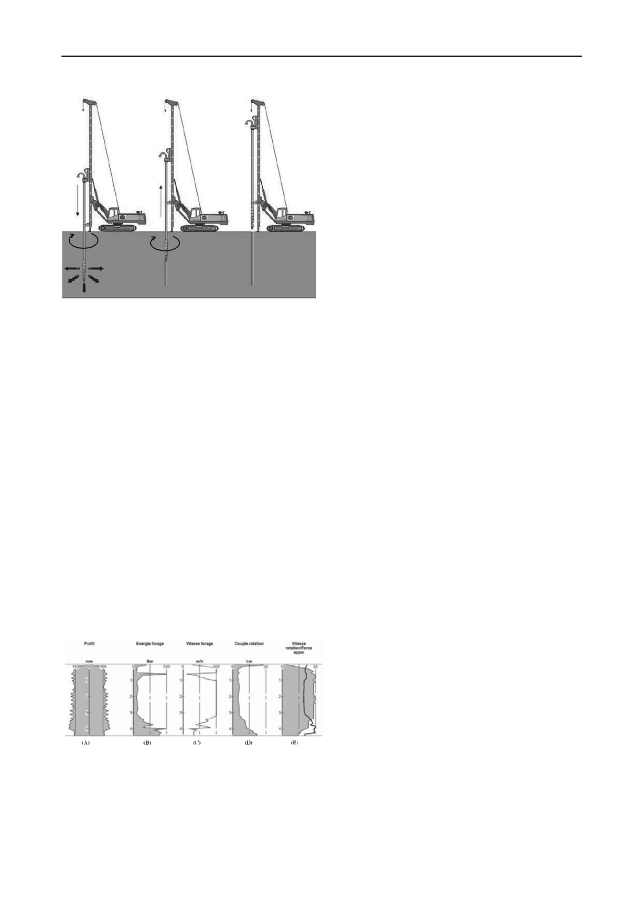
Throughout the process of building an inclusion (Figures 5A,
5B and 5C) real time and continuous monitoring of the
parameters that intervene in its execution are done with
electronic devices located in the cab of the crane. They detect
the signals sent by various sensors installed at strategic points of
the construction equipment. Through this monitoring, the
operator has control of the different construction parameters and
can ensure the quality of the construction of the inclusion at all
times and along its entire height. Among the parameters
controlled are: the drilling depth, the pressure and the volume of
the concrete, the upward and downward speeds, rotation and the
auger's torque.
Given the type of auger used in the construction these
inclusions are defined as displacement inclusions where the
surrounding soil is displaced and laterally compressed at the
moment of drilling, which increases the compactness of soils
whose frictional component is significant.
The equipment is also able to store the record of the controls
for each inclusion, to be processed later on a personal computer.
Continuous records are obtained along the depth(see Figure 6).
During construction of displacement rigid inclusion there is
real-time monitoring of parameters such as drilling depth,
pressure and volume of the poured concrete, advancement speed
and auger rotation, downward force of the rotor torque of the
auger, which ensures a high quality control of the construction.
Due to the advantages provided by the design of soil
improvement systems with rigid inclusions, plus the
geotechnical and environmental benefits of displacement rigid
inclusions, numerous projects worldwide are being approached
with this technique.
5 REFERENCES
Auvinet, G. (2006). “Rigid inclusions in Mexico City soft soils: history
and perspectives”, International Symposium “Rigid inclusions in
difficult soft soil conditions”, Instituto de Ingeniería, UNAM, Cd.
de México.
Combarieu, O. (1988). “Amélioration des sols par inclusions rigides
verticales – Application à l’édification des remblais sur sols
médiocres”. Revue Française de Géotechnique N° 44, 5779.
ASIRI National Project (2012). “Recommendations for the design,
construction and control of rigid inclusion ground improvements”.
Bureau Veritas. “Cahiers des charges CMC”.
Bureau Veritas. “Cahiers des charges Refsol”.
Figure 6. Record of monitoring in continuous real time: (A) Inclusion
profile (mm), (B) Perforation energy (bar), (C) Perforation speed (m/h),
(D) Rotation torque (t.m), (E) Rotation speed / Bearing force.
The start and stop of the concrete pump is wirelessly
controlled by the crane operator from the cab. The speed at
which the auger advances, the rotor torque, the rotation speed
and down force or extracting force of the auger is controlled
manually through the hydraulic system of the crane.


