2454
Proceedings of the 18
th
International Conference on Soil Mechanics and Geotechnical Engineering, Paris 2013
q
Transfer layer
Hard layer
S
d
Compressible soils
Rigid inclusions
Trasfer layer
S
d
Rigid inclusions
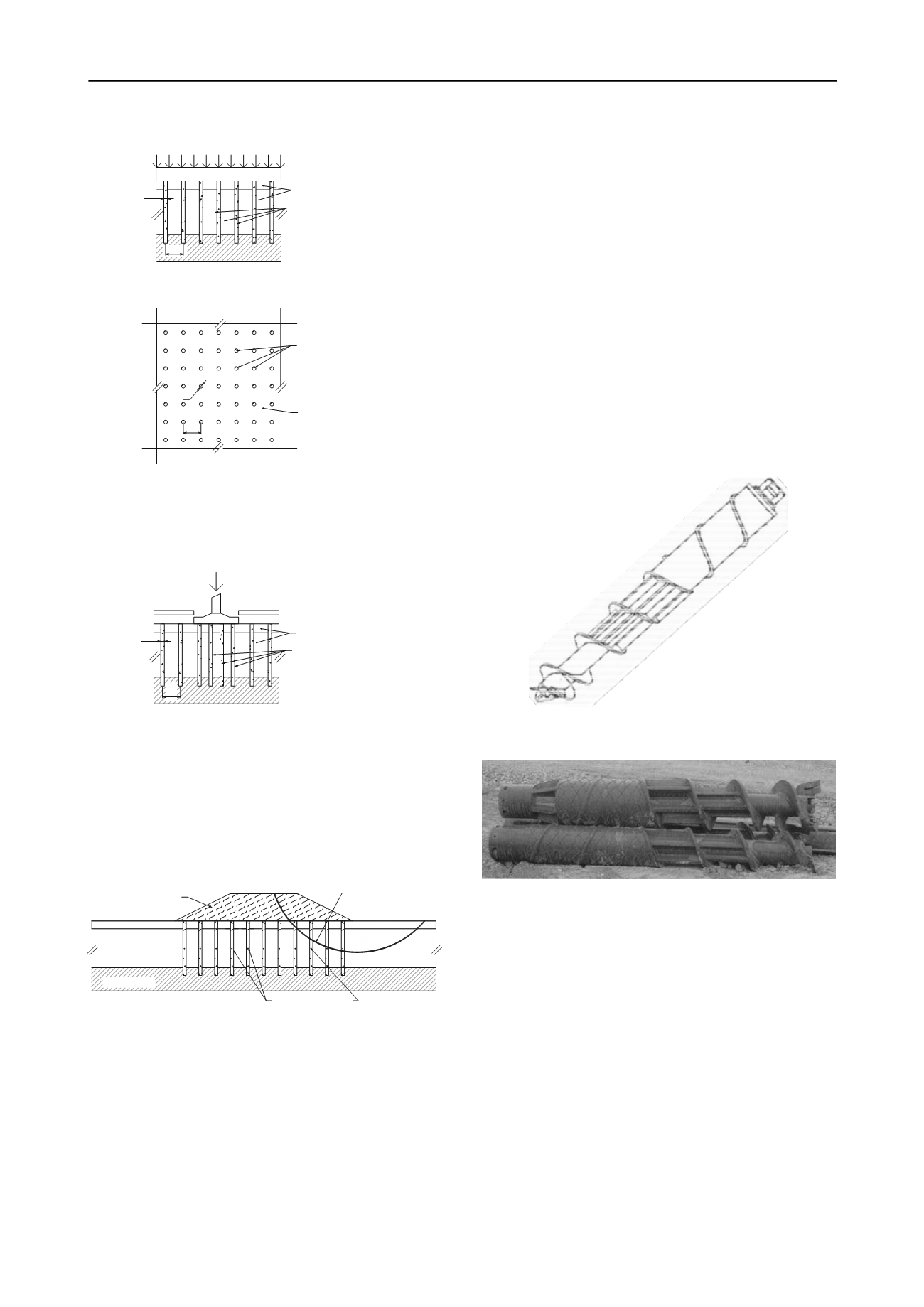
Figure 1. Inclusion under a load uniformly distributed on the surface.
Side and top views.
In this case the LTP may not be required and a significant
portion of the load from the superstructure will be supported by
the grid of inclusions and the remainder will be supported by
the soil surrounding the inclusions —see Figure 2—.
Rigid inclusions
S
q
Hard layer
d
Compressible soils
Figure 2. Model setup of inclusions under an acting strut load on a
footing. Side view.
In the same way that the inclusion-soil system supports
vertical loads —uniformly distributed or concentrated— from
buildings, this application can be extended to the case of
embankments and landfills in which the system will receive the
weight of the material that forms the embankments or landfills.
A particular case occurs when the embankment or landfill is
significantly high and the soil reinforced with inclusions
participates in its stabilization —see Figure 3—.
Rigid inclusions
Failure surface
Compressible
Hard layer
Embankment
soils
Figure 3. Inclusions that help stabilize an embankment or landfill
constructed on the surface.
The inclusions will generally be subjected to the action of
vertical forces caused by discharges from the building or due to
the weight of the embankment or landfill. However, in cases
where the inclusions participate in the stabilization of
embankments or landfills, or when they are subjected to the
action of seismic forces, the generation of lateral forces will
also have to be taken into account in the design.
Several approaches and ways of analyzing and designing
inclusions have been developed. Some of them have been
recently brought together in the ASIRI (
Amélioration des Sols
par Inclusions Rigides
—see ASIRI National Project, 2012—).
3 CONSTRUCTIVE SEQUENCE
The equipment used for the construction of displacement rigid
inclusions kind must circulate over a flat working platform,
drained and stable, generally constructed of granular material.
The inclusions are built from this platform.
The drilling equipment consists of a crane supported on
caterpillars with a cab for the operator and a mast that supports
a cylindrical auger of a defined length. The auger is hollow and
has a special geometry —see Figures 4a, 4b—, capable of
displacing soil laterally when drilling. This is the most
important feature of displacement rigid inclusions because the
surrounding soil becomes laterally compressed. Lateral friction
increases in the case of mainly granular soils or soils with a
large content of sand.
At the bottom part of the tip there is a hinged lid that remains
closed during the drilling phase to prevent the entry of material
into the inner tube and which opens to allow the exit of the
concrete to form the inclusions.
Besides the necessary drilling equipment there has to be a
concrete pump which feeds the upper side of the drilling tool
through flexible hoses.
Figure 4a. Diagram of the typical point of the hollow auger for
displacement rigid inclusions.
Figure 4b. Point of the hollow auger for displacement rigid inclusions
developed for Soletanche-Bachy, RefSol system.
With the topographic location of the inclusion to be built, the
process begins by placing the mast of the crane upright and
lowering the auger into the ground. A rotor torque and a
descending vertical force are applied to the auger to cut,
penetrate and displace the soil laterally. This action is
performed continuously until the drill reaches the specified
depth —see Figure 5A—.
At this point, the concrete is pumped from the tank of the
pump through a flexible hose to the upper part of the hollow
auger to fill it completely and to generate sufficient pressure on
the concrete.


