2176
Proceedings of the 18
th
International Conference on Soil Mechanics and Geotechnical Engineering, Paris 2013
The stabilization measures proposed for all damaged areas
(initial and extended areas) included: surface and subsurface
drainage (sub-horizontal drains), surface protection, placement
of access stairs with surface drainage, modification of slope
shape, installation of retaining walls, definition of areas where
occupation was to be prohibited, definition of houses to be
relocated, dissemination of information to the public, and
raising overall awareness of the conditions, along with
community consciousness. Figure 7 shows some of the
mitigation and control measures proposed.
SM-01
SM-02
SP-01
SP-02
SP-03
54
52
50
48
46
44
42
40
38
36
34
32
30
28
26
24
-5
0
5 10 15 20 25 30 35 40 45 50 55 60 65 70
Distance (m)
Elevation (m)
75 80
Figure 4. Flow Analysis – Pore Pressure Distribution.
28A
156
Houses to be relocated
Solpe modification
Retaining walls
Extension of the area damaged
Surface and subsurface drainage
Surface drainage
Retaining walls
Access stairs - superficial drainage
Retaining walls
Access stairs - superficial drainage
Constructions is not permited
Surface protection
C
DE
TERRA
56
66
46
76
86
96
106
116
126
136
75
85
95
112
146
S/N
145
165
146
25
100
87-A
99
190
80
S/N
S/N
S/N
27
S/N
S/N
316
58
368
145
418
250
100
85
200
130
281
156
227
S/N
S/N
417
29
S/N
S/N
S/N
S/N
60
86
70
50
70
90
32
30
10
65
55
45
35
25
15
05
09
08
26
36
40
S/N
400
35
05
10
14
07
12
71 57
13
40
S/N
S/N
S/N
78
70
103
247
265
265
265
264
85
45
44
43
30
32
29
28
27
26
42
41
IGREJA
21
20
19
10
20
03
430
420
167
405
401
237
581
38
159
158
157
224
S/N
S/N
338
54
111
334
344S/N
112
S/N
S/N
S/N
104
120
90
335
335A
156
09
260
275
315
158
266
ABREU
SUBIDA
DO
VALE
DAS
PEDREIRAS
VILA
RUA
GILBERTO
RUA
RUA
RUACASSIMIRODEABREU
126
335
335
25B
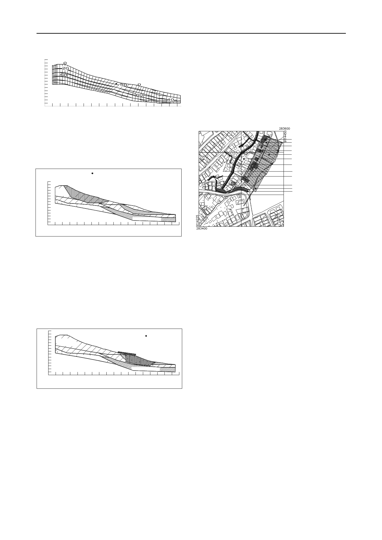
The first landslide occurred between the positions SM 02
and SP-01. For this case, the safety factor value was 1.002,
for practical purposes, considered to be a condition of failure,
and initiating the landslide mechanism in the area (Figure 5).
SM-01
SM-02
SP-01
SP-02
SP-03
Clayey
sand / BF
Silty sand / RS
Sandy clay gray / RS
54
52
50
48
46
44
42
40
38
36
34
32
30
28
26
24
-5
0
5
10 15 20 25 30 35 40 45 50 55 60 65 70 75 80 85
Elevation (m)
1.047
Distance (m)
SM-01
SM-02
SP-01
SP-02
SP-03
54
52
50
48
46
44
42
40
38
36
34
32
30
28
26
24
-5
0
5
10 15 20 25 30 35 40 45 50 55 60 65 70 75 80 85
Distance (m)
Clayey
sand / BF
Silty sand / RS
Sandy clay gray / RS
Clayey sand yellow / RS
Elevation (m)
1.002
Figure 7. Measures Proposed for Mitigation and Control
Figure 5. Back-analysis of the first slope failure – from SM-01 to SP01
The mass that moved in this area (from the first failure)
caused a surcharge estimated at 30KN/m between positions SP-
01 and SP-02, which associated with pore pressure conditions,
provoked the second step of the landslide. With this
understanding, stability analysis was performed (back-analysis)
using geotechnical information from the field and laboratory
investigations. Figure 6 presents the minimum safety factor
value obtained (1.047), confirming the displacements, and the
failure mechanism considered to be the cause of the landslide
that occurred in the area.
5 CONCLUSION
The geotechnical characterization, along with flow and stability
analyses / back-analysis results, were considered to be very
satisfactory, and in accordance with the literature, permitting
that the principal causal factors, and the mechanisms of the
landslide could be comprehended and studied. It was
understood that due to the heavy rainfall, the water level
became elevated, saturating the soil, and producing a
concentrated flow. The strength parameters used in the analysis
were derived from direct shear laboratory tests in the
corresponding condition. Considering all of the information
available, mitigation and rehabilitation measures were then
proposed, generating a risk management program that included
structural and non-structural stabilization actions, considering
the social conditions of the area.
6 ACKNOWLEDGEMENTS
The authors are grateful to the CNPq, FACEPE, and
Camaragibe City Administration for research support, and all
members of the GEGEP/UFPE who participated in the projects.
7 REFERENCES
Figure 6. Back-analysis of the second slope failure – SP-01 to SP-03
After three years, another intense rainfall period amplified the
problem, with cracks forming in many other houses, and
extending the area initially showing damage. See the right side
of the two upper-center squares of Figure 7.
Coutinho, R. Q.; Silva, M. M. and Lafayeete, K. P. V. 2011.
Geotechnical characterization of two unsaturated mature granite
residual soils from Pernambuco, Brazil
. PCSMGE
. CD-ROM
Proceedings, p.7. Toronto, Canada.
Coutinho, R. Q. 2011. Projeto de Estabilização de Encostas no
Município de Camaragibe – PE. Relatório Técnico (“Technical
Report”). Prefeitura de Camaragibe – PE, Brazil.
4 MITIGATION AND REHABILITATION MEASURES
The mitigation and rehabilitation measures consisted of
reducing damage and losses through control of the processes,
and protection of the exposed elements in order to reduce their
vulnerability. During the investigation and studies, it became
possible to understand the processes involved, and to identify
the causal factors and triggering mechanisms in the area. The
general plan was to propose a risk management program that
included both structural and non-structural mitigating actions,
considering the social conditions of the area (Coutinho, 2011).
Silva, M. M.; Coutinho, R. Q. and Lacerda, W. A. 2009. Estudo de um
movimento de massa ocorrido numa encosta em Camaragibe,
Pernambuco.
V COBRAE
. CD-ROM, p. 10. São Paulo, Brazil.
Silva, M. M. and Coutinho, R. Q. 2009. Geotechnical characterization
of an unsaturated residual soil of granite from Pernambuco, Brazil.
17
th
. ICSMGE.
v. 5, 3417-3420. Alexandria, Egypt.
Silva, M. M. 2007. Estudo geológico – geotécnico de uma encosta com
problemas de instabilidade no Município de Camaragibe – PE. Tese
de Doutorado (DSc.). UFPE. Engenharia Civil, Recife-PE, Brazil.


