1576
Proceedings of the 18
th
International Conference on Soil Mechanics and Geotechnical Engineering, Paris 2013
capable of loading and measuring at higher torques and wider
strain ranges. It is a combined resonant column (RC) and
torsional simple shear (TOSS) device. The device can drive a
cylindrical specimen (ID=4.0 cm, OD=6.0cm, L=14cm) in
torsion with the use of permanent magnets and electric coils.
The specimens are covered by latex memebranes inside and out
and are fixed at the base and free to rotate at the top, where the
drive head is attached. The drive head consists of a coil and
magnet system where there is open space between the magnet
and coils. An accelerometer is used for measuring displacement
during RC testing; the nature of acceleration measurement
allows for very high accuracy at low amplitudes (γ=10
-4
%).
Proximitors measure the gap distance between their targets and
are used for measuring rotation (strain) during TOSS tests.
Since they are DC output devices, there is no low-frequency
roll-off as in accelerometer measurements. An LVDT measures
vertical displacement of the drive head. Its inner core is
connected by a rigid threaded rod to the drive head. The other
end of the rod is suspended on a spring, providing a counter-
force to the drive head’s weight without impeding the RC
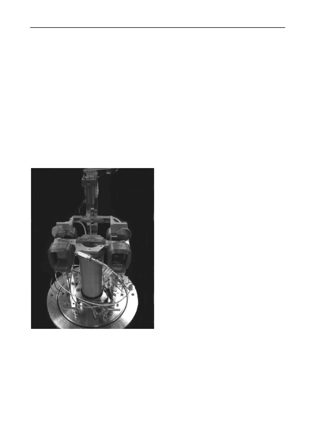
measurements (Figure 2).
Figure 2. RC-TOSS device with hollow-cylinder specimen, coils,
magnets, accelerometer, proximitor targets and LVDT.
The upper and lower specimen ring have a porous interface
and can provide saturation to the specimen. Pore pressures are
measured at the confining cell’s outer port. Due to the extensive
electronics, the confining medium is air.
The driving system allows for individual control of the
applied shear stresses as well as the cell pressure (with use of a
pressure chamber) and the hollow cylindrical specimens have
the great advantage of having nearly-uniform shear stress
distribution throughout its cross-section.
For the RC tests, the specimen is driven in a harmonic
manner back and forth in torsion at very low strain amplitudes
with varying frequencies in order to find resonance. From the
obtained resonance frequency, the shear wave velocity and the
shear modulus can be obtained.
The RC test is capable of measuring the damping ratio as a
function of strain amplitude by either the logarithmic decrement
or half-bandwidth method. For low strain amplitudes, the half-
bandwidth method works well. At higher amplitudes, it is often
difficult to get stable readings and the log-decrement method
generally works better. By using a cutoff switch that turns the
coils into open circuits there is very little coil-generated
damping during log decrement measurements. Additionally, the
drive system can be given an offset DC voltage to apply static
stress/strain then resonated with a low-amplitude signal to
examine effects of different stress ratios (σ
1
/σ
3
) and static shear
stress/strain (τ
static
,γ
static
) on shear modulus.
With use of the data acquisition system and computer,
various cyclic and arbitrary load histories can be applied.
Hysteresis and secant/tangent moduli can then be computed
from the aquired data. The unique design of the testing device
allows for both RC and TOSS tests to be run on the same
specimen any number of times and in any sequence. A
particularly useful sequence is to perform low-amplitude RC
between different stages of TOSS testing to evaluate the effects
of each TOSS stage on the “fundamental” property G
max
. The
baseline value of G
max
allows data to be normalized by
reference strain (γ
ref
) or other quantities. The same values for
G
max
have been produced in bender element tests on triaxial
specimens of the same soil.
The drive system uses a 500-watt DC power amplifier that
can be current-controlled. Under current (rather than voltage)
control, the device can consistently deliver the same stress level
during a test, even if the coils heat up. Using neodymium
magnets, the device can generate shearing stresses greater than τ
= 200 kPa. Driving a specimen at resonance would increase the
available force by a factor of 2-3x.
2.2
RC-TOSS Software
The device is controlled via Visual Basic for applications
(VBA) within Excel. Resonant column testing is normally
performed manually by seeking resonance with a frequency
oscillator, oscilloscope, and precision digital multi-meter.
However, the computer can perform frequency sweeps and
measure accelerometer RMS output and period to capture
resonance as well. More importantly, the TOSS testing can be
performed as stress- or strain-controlled using a variety of
waveforms. Most commonly, triangle wave loading is used for
uniform cyclic loading or cyclic loading with static offset. Data
acquisition of 200 different cycles, 200 data points per cycle are
routine. The number of data points and recorded cycles is
limited only by software memory. Arbitrary loading hisories
can be used as well, most often to study effects of past load
history and verify Masing criteria. Data is reduced and plotted
through VBA and Excel Macros. Further data analysis can be
performed later within Excel.
3 TESTING DANUBE SANDS
Candidates for initial testing were sands of various gradations
found along the main channel and floodplain of the Danube
River. These sands are of particular interest and importance due
to building development along the Danube throughout Hungary,
the widely varying in-situ conditions of the sands, and the
potential for drastic strength reductions and liquefaction during
seismic events.
3.1
Testing Sequence
Initial testing performed on the sands was as much to verify
device performance as it was to establish dynamic properties. In
order to verify proper operation of the equipment, most tests


