1476
Proceedings of the 18
th
International Conference on Soil Mechanics and Geotechnical Engineering, Paris 2013
clay layer and some pile properties related to Offshore Wind
Turbines are less discussed. So in this study, it is intended to
cover some of these issues.
2 CONSTITUTIVE MODEL AND NUMERICAL
FORMULATION
This plasticity model (Parra, 1996, Yang, 2000) is based on the
original framework of Prevost (1985), in which a multi-surface
approach is adopted for cyclic hysteretic response (Iwan, 1967,
Mroz, 1967). The yield function f (Figure 2) is selected of the
following form (Prevost, 1985):
(1)
In the domain of p’≥0, where s=σ’-p’δ is the deviatorice stress
tensor, p’ is mean effective stress, p’
0
is a small positive
constant such that the yield surface size remains finite at p’=0. α
is second-order kinematic deviatoric tensor defining the yield
surface coordinates and M dictates the yield surface size.
Figure 2.Conical yield surface in principal stress space and deviatoric
plane (after Prevost, 1985; Parra, 1996; Yang 2000).
In this model, the contractive, perfectly plastic and dilative
phases of Figure 3 are incorporated by developing a new
appropriate flow rule.
Figure 3.Schematic of constitutive model response showing shear stress,
effective confinement and strain relationship [1].
For solving the governing equations of the fully coupled
soil-fluid medium, the matrix form of formulation is as follows:
(
2)
(3)
In these equations, M, B, Q, S and H are matrices ofmass,
strain-displacement, coupling, compressibility and permeability
respectively. Vectors f
(s)
and f
(p)
dictate the boundary conditions
of model including body and surface forces in soil and fluid.
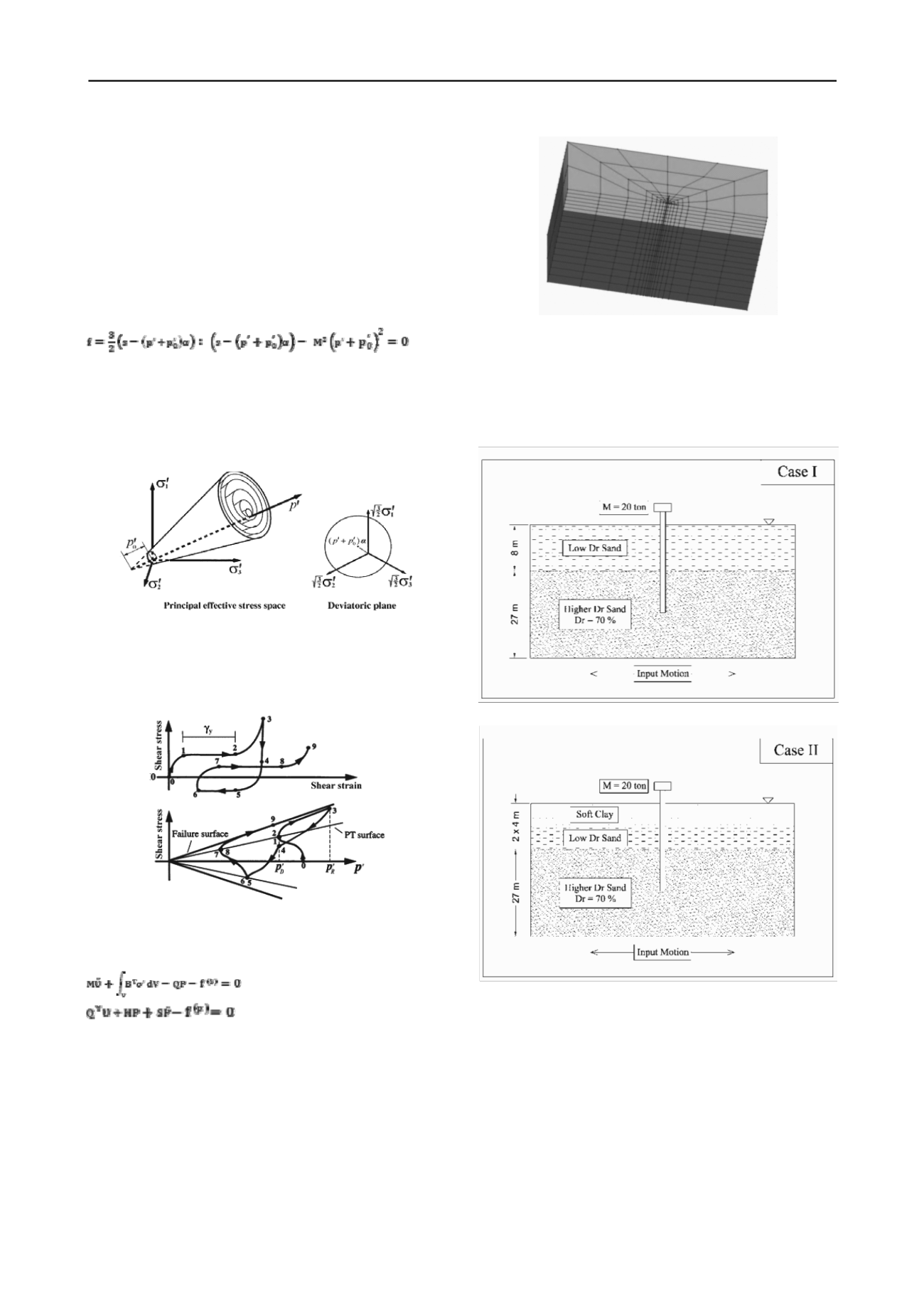
3 MODEL DESCRIPTION AND VERIFICATION
Model is built using OpenSeesPL.Soil dimension is 60x30x35
m in x,y and z directions respectively as shown in Figure 4.
Figure 4. 3D model used in this study
Two general cases for soil layers are considered. For Case I
as shown in Figure 5, a sand deposit of 8 m thickness with
relative density of 40% is placed over a sand layer with D
r
=70%
and thickness of 27 m. For Case II in Figure 6, half of the first
layer is replaced with a very soft clay. The sand properties are
shown in table 1. For very soft clay, shear modulus is 1000 kPa
and cohesion is 15 kPa.
Figure 5. Schematic of Case I
Figure 6. Schematic of Case II
Every node has 4 degrees of freedom(DOF). The first three
DOFs represent soil translation in x,y and z directions and the
4th DOF is for pore water pressure. Base nodes are fixed in all
directions. Pore pressure degree of freedom is fixed in ground
surface to let the water to drain at this region and is open to
change in other nodes. Side nodes perpendicular to base motion
direction are fixed in this direction and are open parallel to
excitation direction. Side nodes parallel to base excitation are
constrained perpendicular to excitation direction and free to
move in this way. To prevent sides of the model from reflecting
dynamic waves, large elements are put in these regions.
Pile properties are selected as follows: diameter = 1 m,
length = 21, length above surface = 1 m, thickness = 1 cm,
Modulus of Elasticity = 30 GPa, pile head is free to rotate and
the material behavior is elastic.Pile elements are connected to


