1238
Proceedings of the 18
th
International Conference on Soil Mechanics and Geotechnical Engineering, Paris 2013
loads. Given the non-linear resilient characteristics of soils and
granular materials, it is important to use an appropriate stress
level when testing. If a hand-held Lightweight Deflectometer
(LWD) is used, the stress level will be lower and the zone of
influence smaller so a correlation exercise with the FWD has to
be carried out and this is site specific.
In order to assess resistance to rutting, a standard truck of
known axle load is operated on the completed foundation to
deliver the equivalent of 1000 standard 80kN axle loads. The
accumulated permanent deformation in the wheel tracks is
measured and assessed against allowable values which depend
on the layer thicknesses and material types.
During the design phase, it is convenient to use a simple
laboratory test to determine the resilient characteristics of
potential materials for use in the foundation. This provides input
data to the design analysis which can generate a combination of
layers of particular thicknesses with an overall effective surface
modulus to satisfy the design specification for one of the
foundation classes. A site trial involving one or more potential
solutions can then provide confirmation that the target surface
modulus has been achieved.
3 LABORATORY TESTING
3.1
Background
The testing philosophy is an extension of that adopted for
asphalt, which resulted in the Nottingham Asphalt Tester
(NAT), (Cooper and Brown, 1989) being developed as a simple
low cost facility for use in engineering practice. It consisted of a
pneumatically driven loading frame into which different test
modules could be placed in order to measure various
mechanical properties of an asphalt test specimen under
repeated loading, including stiffness modulus, resistance to
fatigue cracking and to permanent strain accumulation.
Using similar principles to those applied by Semmelink and
de Beer (1995) for their K-Mould, Edwards et al (2005)
developed a test module for unbound and weakly stabilized
materials (known as a ‘Springbox’) that fitted into the NAT test
frame. This involved a 170mm cubical specimen contained in a
box with one opposite pair of vertical faces rigid and the other
pair spring loaded to simulate the confining situation insitu for
an element of compacted aggregate. Vertical loading was
applied through a square loading platen at a frequency of 1Hz
by the pneumatic actuator and measurements of both resilient
and plastic deformations were taken under repeated loading.
3.2
The Precision Unbound Materials Analyzer (PUMA)
One of the perceived disadvantages of the Springbox is its
square cross-section, raising the possibility of non-uniform
compaction and non-homogeneous stress conditions. The
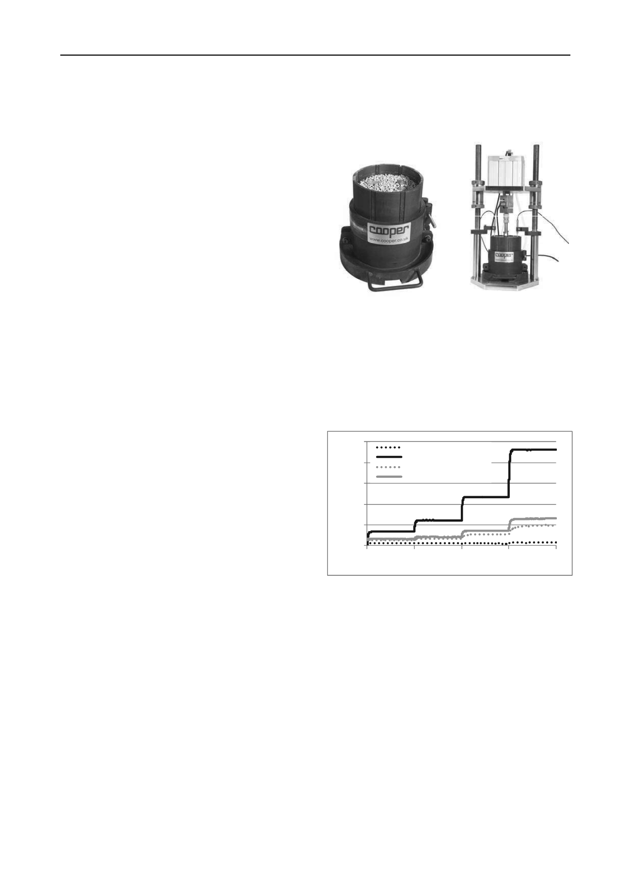
PUMA, shown in Figure 1, therefore, adopts a similar 150mm
diameter circular shape to that of the K-Mould but with a
slightly increased height of 150mm. Like the K-Mould it is
confined within eight curved wall segments. The specimen,
which is compacted using standard equipment (e.g. a vibrating
hammer) at a desired water content, is then loaded on its top
surface by a circular platen. Side walls are confined within a
rubber-lined steel band, the rubber providing the possibility of
wall movement under load, simulating the elasticity of
surrounding material in-situ. Under repeated vertical loading a
residual horizontal stress will accumulate, typically between
10kPa and 50kPa, again simulating the in-situ condition.
Measurements are taken as follows: a) vertical load from a
load cell; b) vertical displacement of the top surface from
LVDTs, optionally inserted through holes in the top platen; c)
horizontal strain in the steel confining band from a strain gauge.
This last measure is directly proportional to the stress in the
steel band and, therefore, to the horizontal stress in the
specimen. It is also proportional to the horizontal strain in the
specimen, via the known compressibility of the rubber lining.
Thus, while only vertical stress is controlled, vertical and
horizontal stress and strain are all monitored during the test.
Figure 1. The Precision Unbound Material Analyzer (PUMA)
3.3
Analysis of Test Conditions
In order to maximize the information that could be derived from
a single test during the development of the equipment,
specimens were loaded in four stages each involving 1000 load
applications. Vertical stress levels up to about 250kPa were
used, above an initial preload of typically 5kPa. Since
horizontal stress is not controlled, values varied according to the
material tested. Figure 2 illustrates stresses measured during a
typical test on a natural gravel.
0
50
100
150
200
250
0
1000
2000
3000
4000
Stress during test (kPa)
Number of load applications
Vertical stress ‐ min
Vertical stress ‐ max
Horizontal stress ‐ min
Horizontal stress ‐ max
Figure 2. Stresses measured during a typical PUMA test
As a first approximation, friction between the walls and the
specimen could be neglected and the measured stresses and
strains converted directly into a stiffness modulus and Poisson’s
ratio, treating the material as a linear elastic solid. This is the
method specified in EN 13286-7 (CEN, 2004) in relation to
interpretation of triaxial data. Nevertheless, it is self-evidently
inaccurate to ignore friction between the walls and the specimen
as well as friction against the upper and lower platens. Direct
measurements taken during development of the PUMA
equipment suggested that a coefficient of friction of around 0.5
could be expected. The effect of this would be to transfer
vertical load to the walls, reducing the stress at the lower platen.
Similarly, platen friction would mean that not all the internal
horizontal stress within the specimen would reach the walls and
be measured. An approach to take account of this has been
outlined by Thom et al (2012) who developed the following
correction equations.
v(corrected)
=
v(measured)
– 0.5μh (
hmax
+
hmin
)/r
(1)
h(corrected)
=
h(measured)
+ 2μr (
vmax
+
vmin
)/15h
(2)


