1228
Proceedings of the 18
th
International Conference on Soil Mechanics and Geotechnical Engineering, Paris 2013
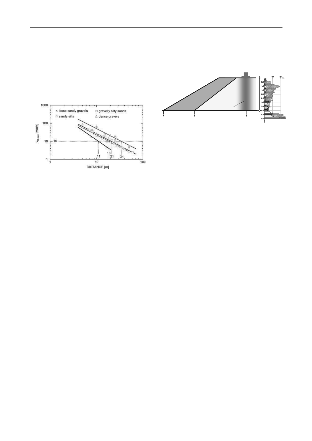
practically identical for dense gravels, sandy silts, and gravelly
silty sands. The results show that the peak velocity magnitude
falls below the value of max v
R,max
= 10 mm/s, i.e. the limit
value for buildings of the class no. III according to the Austrian
Standard ÖN S 9020, at a distance of 11 to 34 m from the
impact foot, depending on the subsoil condition and soil type.
Based of hitherto experience the required minimum distance to
buildings of class no. III is about 20 m. In comparison
compaction of heavy tamping techniques induces resulting
velocities of more than 10 mm/s at a distance of 30 m.
Figure 7. Magnitude of maximum resulting velocity as function of the
distance from the impact foot. Measured values for different soil types.
4 SELECTED CASE HISTORIES
4.1
Ground improvement for embankments and foundations
In the last five years the standard application for the Impact
Compactor was the ground improvement for embankments and
foundations. Typical fields of application are:
improvement of the ground in the embankment base
compaction to increase the bearing capacity of foundations
and/or reduce the liquefaction potential of soils
improvement of the ground bedding conditions for slabs
combined application with other compaction methods such
as heavy tamping or deep vibro-compaction when large
compaction depth is required, or lime stabilization of soft
cohesive soils on top of the ground (Adam et al. 2010)
4.2
Rehabilitation of flood protection dikes
The efficiency of the Impact Compactor to improve existing
flood protection dikes alternatively to e.g. the mixed-in-place
method (MIP) was investigated by compaction of the core of a
test dike (Adam et al. 2010).
The test dike was constructed on a gravelly ground, which is
covered with a loess layer of about 0.75 m thickness. The core
of the embankment was built layer-wise with a layer thickness
of about 1 m. Each layer was only “pre-compacted” with a
vibratory roller in order to simulate the weak compactness of
existing old flood protection dikes. For one half of the
embankment core sandy silt (loess) was used as filling material,
for the other half silt (loam). The shoulders and slopes were
constructed with sandy gravel (see Figure 8).
Optimization and control of compaction was realized by the
following tasks and criteria:
meeting the stop code criteria
GPS-based documentation of the compaction parameters
performance of dynamic probing heavy (DPH) before and
after compaction
performance of dynamic load plate test using the LFWD
before and after compaction
in-situ permeability tests
In the following selected results of dynamic probing tests are
presented exemplary, which were carried out to determine the
compaction depth. Figure 8 (right) illustrates the number of
blows N
10
over depth determined with dynamic probing heavy
in the test section consisting of loess. It is obvious that the depth
effect of the Impact Compactor is about 4.5 m. Figure 8 reveals
that the upper zone of the gravelly ground beneath the
embankment was compacted as well.
depth [m]
4.5 m
12.0 m
4.0 m
gravel
core
(loess / loam)
compacted zone
N
10
BEFORE RIC
AFTER
RIC
Figure 8. Section of the test dike (left) and Dynamic Probing Heavy in
the loess (right).
5 CONCLUSION
In Central Europe the Impact Compactor was introduced in
2007. The novel compaction equipment provides a technically
sound and economic method of improving the capacity of a
wide variety of loose soils (silts, sands, gravels, cobbles,
boulders) and fills. The effective treatment depth in soils is
dictated by grain sizes and is typically in the range of 4.5 m (silt
and sand) up to 7.5 m (10 m) depth (sand and gravel). Due to
the numerous benefits, e.g. monitoring of the compaction
process through a GPS-based recording system (on-board
computer), reliability and safety in operation, quality assurance,
versatility and working speed, the Impact Compactor is now a
well established dynamic compaction method throughout
Europe.
6 ACKNOWLEDGEMENTS
The Austrian Research Promotion Agency (FFG) has funded
this research project. This support is gratefully acknowledged.
7 REFERENCES (TNR 8)
Adam D., and Paulmichl I. 2007.
Impact compactor – an innovative
dynamic compaction device for soil improvement.
In: Proc. 8th
International Geotechnical Conference (June 4-5, 2007, Slovak
University of Technology, Bratislava, Slovakia), pp. 183-192.
Falkner F.-J., Adam C., Paulmichl I., Adam D., and Fürpass J. 2010.
Rapid impact compaction for middle-deep improvement of the
ground – numerical and experimental investigation.
In: 14th
Danube-European Conference on Geotechnical Engineering "From
Research to Design in European Practice", June 2-4, 2010,
Bratislava, Slovakia, CD-ROM paper, 10 pp.
Adam C., Falkner F.-J., Adam D., Paulmichl I., and Fürpass J. 2010.
Dynamische Bodenverdichtung mit dem Impulsverdichter (Dynamic
soil compaction by the Rapid Impact Compactor
, in German
).
Project No. 815441/13026 – SCK/KUG, Final report for the
Austrian Research Promotion Agency (FFG), 184 pp.
Adam C., Adam D., Falkner F.-J., and Paulmichl I. 2011.
Vibration
emission induced by Rapid Impact Compaction.
In: Proc. of the 8
th
International Conference on Structural Dynamics, EURODYN
2011, p. 914-921, 4 – 6 July 2011, Leuven, Belgium.
Fürpass J., and Bißmann, M. 2012.
5 Jahre Impuls-Verdichtung in
Europa. Rückblick auf ein Erfolgsmodell
(in German). In: 2.
Symposium Baugrundverbesserung in der Geotechnik, p. 149-163,
13 – 14 September 2012, Vienna, Austria.


