1227
Technical Committee 202 /
Comité technique 202
tool, and a work integrated quality control. Thus, local
heterogeneities of the subsoil can be identified, and compaction
with the Impact Compactor can be adjusted systematically. If
necessary, additional compaction passes are conducted.
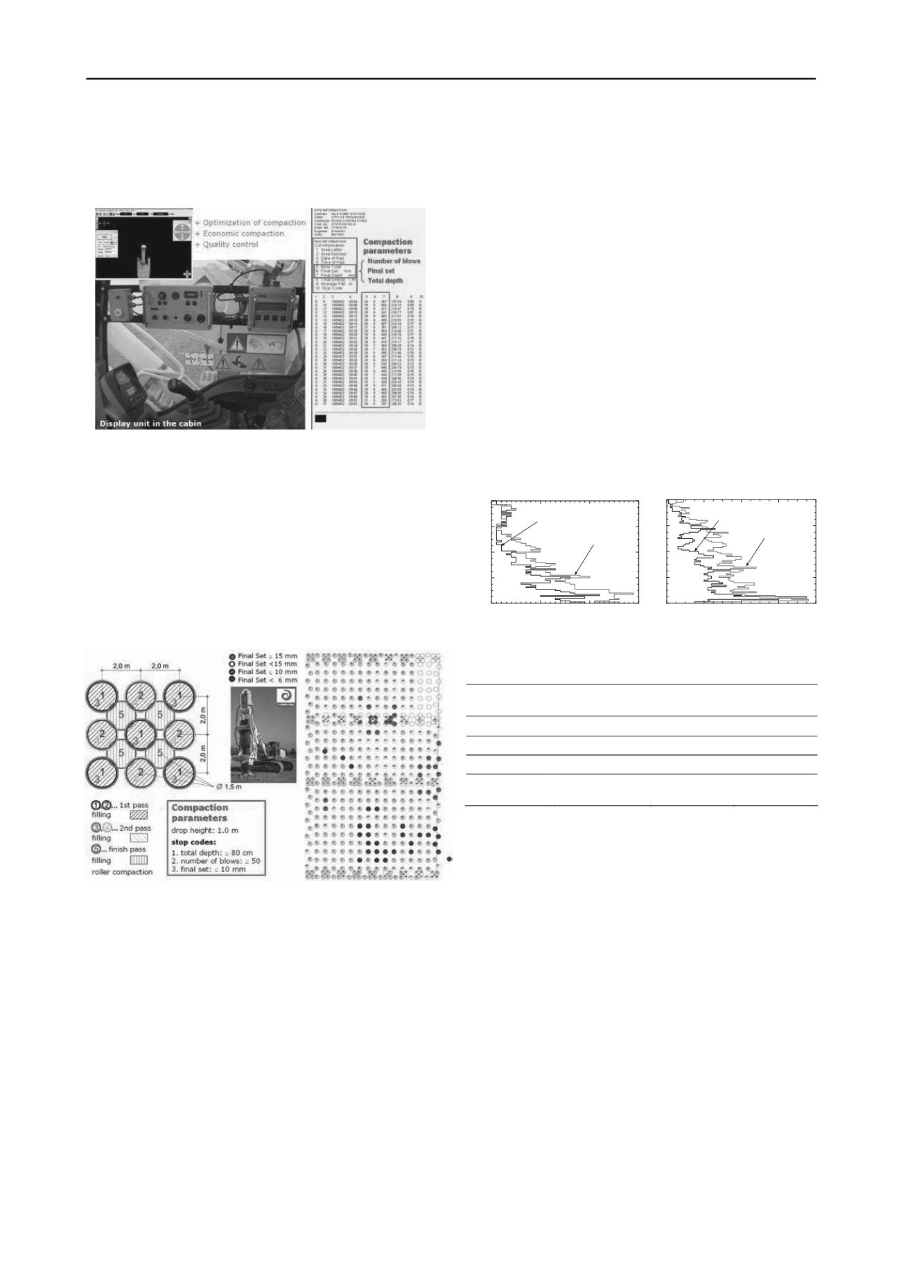
Figure 4. GPS-based recording system of the Impact Compactor.
3.2
Parameter setting and quality control
Optimization and control of compaction with the Impact
Compactor is ensured by meeting the stop code criteria, GPS
based compaction including work integrated documentation of
the performance parameters for each compaction spot, and
conduction of cone penetration tests and/or dynamic probing
before and after compaction. During the compaction process the
following stop codes are applied:
stop code 1: total settlement (depth of the compaction crater)
stop code 2: number of blows per compaction point
stop code 3: final settlement of the last blow
Figure 5: Compaction process (left) and compaction control (right).
The stop codes have to be verified and optimized on a test
field that is located within the site (see Figure 5). In dependence
of the subsoil conditions and the complexity of the project the
calibration field can comprise up to three different compaction
patterns and point grids. The compaction process at the test field
is usually carried out by applying stop codes defined by a
geotechnical expert based on the results and experiences from
comparable sites. After the test compaction the treatment depth
is determined and compared with the required compaction depth
in order to find the suitable compaction point grid. The
compaction pattern and point grids, the number of compaction
passes and the stop codes are finally defined by the geotechnical
expert.
The compaction depth is determined conducting cone
penetration tests (CPT) and/or dynamic probing light, medium,
or heavy (DPL, DPM, or DPH).
In Figure 6 the number of blows N
10
determined by dynamic
probing heavy and light before and after compaction is plotted
against the depth. The dynamic probing heavy was performed in
non-cohesive primarily sandy gravelly soil; the dynamic
probing light was carried out in cohesive soil consisting of silts
and sands. It can be seen that the depth effect of the Impact
Compactor depends on the soil condition, and it varies from
about 4 m (silts and sands) to 7 (8) m (sandy gravelly soils).
In cohesive soils of soft to stiff consistency dynamic probing
heavy allows only a low number of blows independent of the
degree of compaction. Consequently, for checking the
compaction effect it is recommended to use dynamic probing
light (DPL) or cone penetration tests (CPT) (Adam et al. 2010).
Typical depths of influence (treatment depth) are
summarized in Table 1 in dependence of the soil type based on
the results of numerous experimental investigations.
For quality control recorded compaction parameters are
evaluated graphically. As an example, in Figure 5 (right) the
“final set” (stop code 3) is used as control criteria, and the
compaction points are hatched in blue, green, yellow or red
color in dependence on the numerical value of the recorded
“final set”. It can be seen that another compaction pass had to
be carried out on the red colored points. Consequently, this plot
gives information on the compaction quality (whether the stop
codes are met all over the site or not), and allows conclusions to
be drawn about the subsoil quality before compaction.
0
10
20
30
-8
-6
-4
-2
0
before compaction
after compaction
number of blows N10(DPH)
(a)
depth [m]
0
20
40
60
80
-8
-6
-4
-2
0
number of blows N10(DPL-5)
before compaction
after compaction
(b)
depth [m]
Figure 6: Dynamic Probing Heavy (DPH) in non-cohesive soil (left) and
Dynamic Probing Light (DPL-5) in cohesive soil (right).
Table 1. Characteristic compaction depth for the Impact Compactor
ith a falling weight of 9,000 kg mass.
w
Type of soil
Type of dynamic
probing
Number of
blows
Treatment
depth
Sa/Gr
DPH
N
10
> 20
6 – 7.5 (10) m
si Sa
DPH
N
10
> 15
5 – 6 m
sa Si
DPL
N
10
> 20
4.5 – 5 m
Miscellaneous
graded soils
DPL/DPH
N
10
> 15 / 20
4.5 – 7 m
3.3
Vibration emission and immission
On numerous test sites the maximum surface velocity induced
by the Impact Compactor as function of the distance were
determined. The data acquisition tool MR2002DIN-CE (RED
BOX) of the company SYSCOM was applied to monitor and
record the vibrations. The velocities were measured in situ with
tri-axial velocity transducers according to the German Standard
DIN 45669 and saved with a data recorder. The velocity was
measured in three orthogonal directions in the frequency
domain of 1 to 315 Hz. The subsequent data processing was
done with the software package VIEW 2002 (Ziegler
Consultants). Subsequently, regression analyses were performed
to obtain the magnitude of the maximum resulting velocity
v
R,max
as function of the distance from the impact foot.
Figure 7 shows selected linear regression lines for different
homogeneous ground conditions determined through free-field
velocity measurements during impact compaction with a falling
weight of 9,000 kg mass. It is seen that smallest peak velocity
magnitudes develop during compaction of homogeneous loose
sandy gravels. For this subsoil condition a coefficient of decay
of about 1.8 is determined. Note that only one compaction pass
was performed. Largest peak velocity magnitudes were
measured during compaction of dense gravels. Compaction of
sandy silts and gravelly silty sands led to peak velocity
magnitudes in-between. The coefficient of decay of about 1.3 is


