1217
Technical Committee 202 /
Comité technique 202
Figure 11. In-situ response of the ballast layer: lateral deformations
(Source: Fig 4, Indraratna et al. 2013).
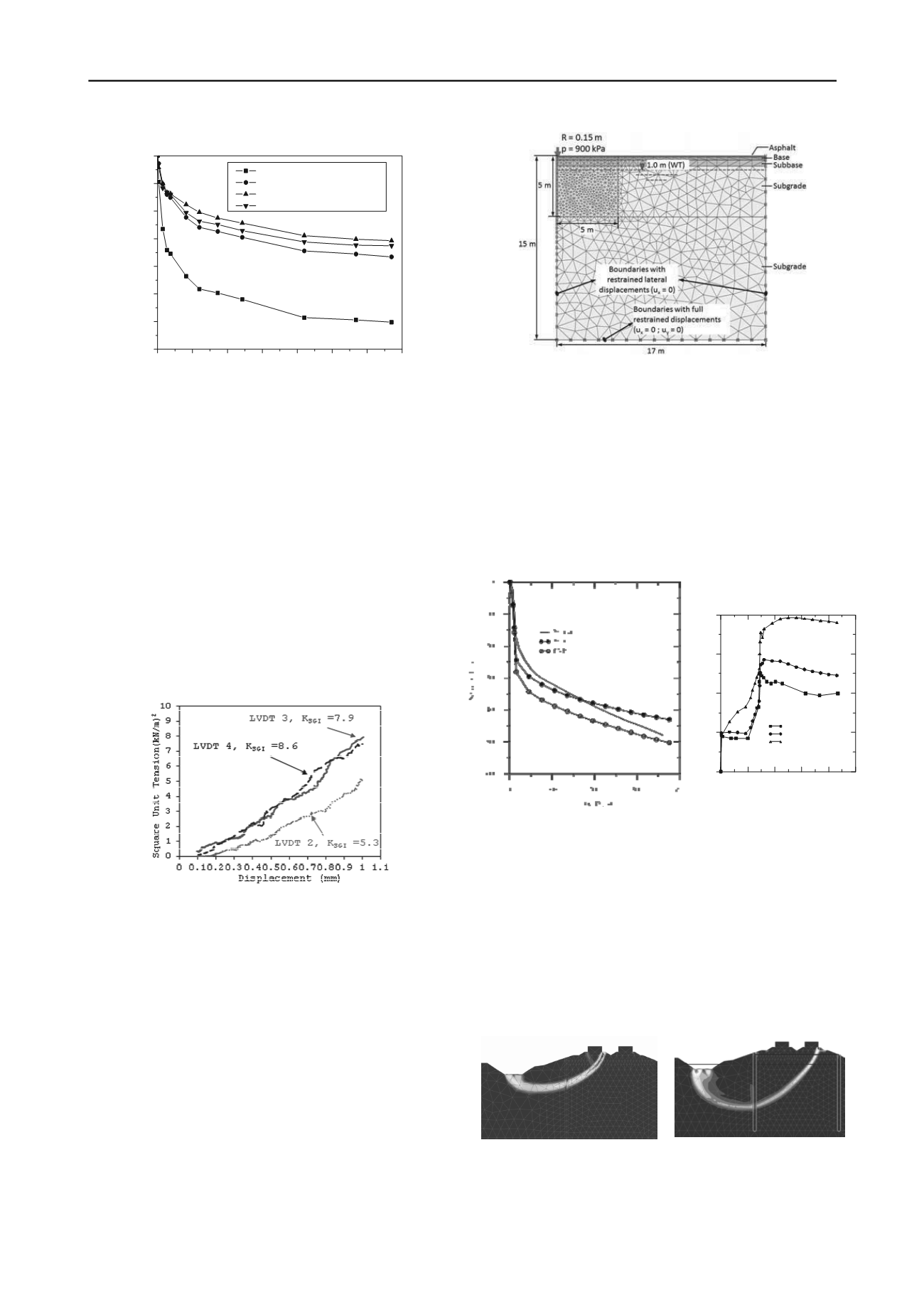
Zornberg et al. (2013) introduced a mathematical model to
investigate the soil-geosynthetic interaction behavior under
small displacements. A new parameter, defined as ‘Stiffness of
Soil-Geosynthetic Interaction’ (K
SGI
) is proposed to evaluate
soil-geosynthetic interaction. This parameter is capable of
quantifying the performance of geosynthetic reinforcement
under small displacement conditions. K
SGI
was proposed on the
assumption of a linear relationship between unit tension and
strain in geosynthetic reinforcement and uniform soil-
geosynthetic interface shear over the active length of the
geosynthetic. Zornberg et al. (2013) conducted several
geosynthetic pullout tests of biaxial geosynthetic with
dimensions of 300
600 mm in clean poorly graded sand to
validate the proposed model. Figure 12 shows a good agreement
between the experimental data and the results obtained with the
proposed model.
Figure 12. Results for the pullout test for LVDTs 2, 3, and 4 in (T
2
-u)
space (Source: Fig 7, Zornberg et al. 2013).
6 NUMERICAL MODELLING
1.1
Finite element modelling (FEM)
There are 5 articles described in this section. The majority of the
papers discusses Finite Element Modelling (FEM) on the
stability analysis of soft clay subgrade and embankments
(Carvajal and Romana 2013, Mansikkamaki and Lansivaara
2013, Islam et al. 2013 and Chirica et al. 2013), while one paper
examines the application of a stochastic subsoil model on the
deformation of bridge piers considering the soil heterogeneity
(Jacobse et al. 2013).
Carvajal and Romana (2013) developed a FEM model of a
multilayered system to investigate the influence of soft soil
depth on pavement response during static and cyclic loading
(Figure 13). They concluded that deep ground treatments should
be applied to achieve an allowable capacity of soft soils up to a
depth of 6 m to reduce the maintenance costs.
0
1x10
5
2x10
5
3x10
5
4x10
5
5x10
5
6x10
5
7x10
5
-14
-12
-10
-8
-6
-4
-2
-0
Average lateral deformation of ballast, (S
h
)
avg
(mm)
Fresh ballast (uniformly graded)
Recycled ballast (broadly graded)
Fresh ballast with geocomposite
Recycled ballast with geocomposite
Number of load cycles, N
Figure 13. Geometry of the finite element model (Source: Fig.1c,
Carvajal and Romana 2013).
Islam et al. (2013) investigated the long-term performance of
the instrumented preloaded Nerang-Broadbeach Roadway
(NBR) embankment founded on a soft sensitive estuarine clay.
Fully coupled nonlinear Finite Element Analyses (FEA) were
carried out adopting an elasto-viscoplastic (EVP) and an elasto-
plastic Modified Cam Clay (MCC) constitutive model. It was
concluded that the MCC model under-predicted the ultimate
settlement whereas the creep-based EVP model captured
settlement quite well, albeit over-predicting the pore pressure
response (Figure 14).
0
50
100
150
200
250
Days
0
20
40
60
80
Excess PoreWater Pressure (kPa)
PP1
MCC
EVP
Figure 14. Comparison of measured and predicted settlements and pore
water pressures (Source: Figs. 4 and 5, Islam et al. 2013).
Mansikkamaki and Lansivaara (2013) introduced a 2D and
3D FEM analysis to evaluate the embankment stability of slopes
reinforced with a wooden pile structure and a sheet pile wall.
Wooden piles and sheet pile walls can be used to improve
embankment stability if the supporting forces are reasonable.
FEM can provide valuable additional information to evaluate
how sensitive the structural forces can be for the soil strength
variation and also to determine what would be the real nature of
the failure. Figure 15 shows the failure surfaces observed with
and without reinforcement.
(a)
(b)
Figure 15. Failure surfaces from the safety analysis. (a) without the
reinforcement (b) with the sheet pile wall (Source: Fig 8, Mansikkamaki
and Lansivaara 2013).


