1216
Proceedings of the 18
th
International Conference on Soil Mechanics and Geotechnical Engineering, Paris 2013
distribution on those GR strips. This is in agreement with the
observations in scaled-down model tests, numerical analysis and
field measurements.
Fernandes et al. (2013) carried out a 2D finite element model
with a modified width (plane strain) where viscous boundaries
are implemented using a Kelvin-Voigt viscoelastic mechanical
model to reduce the wave reflexion on the boundaries. The
importance of initial state evolution of track materials on the
context of non-linear mechanical behaviour is discussed to
assure the correct combination of laboratory tests based on the
current track conditions, especially for ballast (Figure 7).
Figure 7. Finite element mesh discretisation of the railway structure
(Source: Fig 3, Fernandes et al. 2013).
5 APPLICATIONS OF GEOSYNTHETICS
In this section, 4 articles are described. The majority of articles
discuss general issues of geosynthetic reinforcement (Indraratna
et al. 2013, Wayne et al. 2013, Huckert et al. 2013), while other
article examines the stiffness of the soil-geosynthetic
intereaction under small displacement conditions (Zonberg et al.
2013).
Huckert et al. (2013) presented full-scale experiments to
study load transfers of geosynthetics-reinforced embankments
prone to sinkholes which are related to the complexity of
various mechanisms. Numerical model coupling both finite and
discrete element methods were performed and the results
compared with the experimental data. These simulations
provide a better understanding of load transfers towards the
edges of the cavity.
Wayne et al. (2013) presented results of two field studies and
model tests to evaluate performance of a geogrid-stabilized
unpaved aggregate base overlaying relatively weak and non-
uniform subgrade soils. Piezoelectric earth pressure cells (EPC)
were used to measure horizontal stress below and above the
geogrid location versus the passage of construction and truck
traffic. The variation of dynamic horizontal stresses within the
subgrade against the passage of truck traffic is presented in
Figure 8. This result indicated an enhanced fully confined zone
above the geogrid, resulting in an uniform vertical stress across
the subgrade that leads to reduced lateral stresses.
25
20
15
10
5
0
50 100 150
Unstabilised section
Stabilised section
Roller/Test cumulative pass count
Stress (kPa)
Figure 8. Horizontal stress within the subgrade layer after roller
compaction and test vehicle passes (Source: Fig 3, Wayne et al. 2013).
Figure 9 presents the horizontal stress in the base layer after
roller compaction and trafficking. It is clearly seen that the
geogrid confines the unbound aggregate leading to an increased
lateral stress within the aggregate. The results demonstrate that
the inclusion of geogrid at the interface of soft subgrade and
aggregate layers affects the development of the “locked-in”
horizontal stress upon loading. A higher horizontal stress within
the sttabilized aggregate layer gives a direct indication of the
lateral restraint mechanism. The result of increased aggregate
stresses leads to an increase in the resilient modulus of
aggregate adjacent to the geogrid.
25
20
15
10
5
0
50 100 150
Unstabilised section
Stabilised section
Roller/Test cumulative pass count
Stress (kPa)
Figure 9. Horizontal stress within the base layer after roller compaction
and test vehicle passes (Source: Fig 4, Wayne et al. 2013).
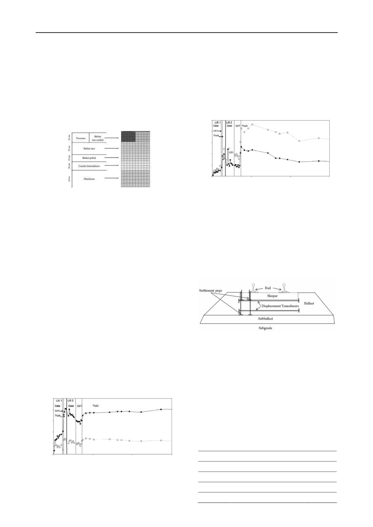
Indraratna et al. (2013) presented the results of full-scale
field tests conducted on rail track sections in the towns of Bulli
and Singleton (NSW, Australia) to measure track deformations
associated with cyclic stresses and impact loads. The vertical
and horizontal stresses induced in the track bed were recorded
by pressure cells. Vertical deformations of the track were
measured by settlement pegs, and lateral deformations were
measured by electronic displacement transducers. The
settlement pegs and displacement transducers were installed at
the
sleeper-ballast
and
ballast-subballast
interfaces,
respectively, as shown in Figure 10.
Figure 10. Installation of settlement pegs and displacement transducers
at Bulli site (Source: Fig 3, Indraratna et al. 2013).
The average lateral deformations of ballast at various
number of load cycles (N) are illustrated in Figure 11. It is
shown that the geocomposite decreased the lateral deformation
of fresh ballast by about 49% and that of recycled ballast by
11%. The capacity of the ballast to distribute loads was
improved by the placement of the geocomposite, which
substantially reduced settlement under high repeated loading.
Indraratna et al. also discuss the results of large scale drop-
weight impact testing equipment to evaluate the effect of using
shock mats in mitigating ballast breakage. The ballast breakage
was measured using the ballast breakage index (BBI) as shown
in Table 1. Installing layers of synthetic materials such geogrids
and rubber pads (shock mats) in rail tracks was found to
significantly reduce ballast degradation.
Table 1. Ballast breakage under impact loading (Source: Table 1,
Indraratna et al. 2013)
Base
Test Details
BBI
Stiff
Without shock mat
0.170
Stiff
Shock mat at top and bottom
0.091
Weak
Without shock mat
0.080
Weak
Shock mat at top and bottom
0.028


