1134
Proceedings of the 18
th
International Conference on Soil Mechanics and Geotechnical Engineering, Paris 2013
0
m
CSC f
dz
(1)
where,
f
(
θ
) is mathematic function for wetting branch of soil
water retention curve, z is elevation above a vertical datum.
However, not all of this stored water can be absorbed by
plants. The minimum water content the plant requires not to wilt
is permanent wilting point,
θ
pwp
, which is defined as the water
content at -1500 kPa of suction. Evaporation can also reduce
water content of soil to residual condition, e.g. this value can be
generally considered as zero for sandy soil. However, the
evaporation processes mainly influence the area near ground
surface. Considering the capillary enhancement system is buried
at certain depth in the ground, the stored water within the
system is only removed by plants. The available capillary
storage capacity (ACSC) can be written as follows
PWP
ACSC CSC m
(2)
For every growing season, the amount of transpiration shows a
parabola relationship with time. When the transpiration rate
becomes low, the plant will become dormant. Thus if the stored
water exceeds the amount of transpiration during the whole
growing season, the plant can live with the support of the
system. The designation of the system needs the information of
available capillary storage capacity, which is relevant to the
thickness, depth of soil layer. However, it is not good to design
a soil layer with great thickness, since the zone, which is deeper
than the root does not provide direct effort to the growth of
plant. Integrating the volumetric water content over the depth of
the overlying horizontal layer yields total water in plate.
Figure 1 Concept of the capillary storage capacity and available
capillary storage capacity
There are several designed functions of the self-watering
system. First of all, the system can continuously supply water to
fulfill the requirement of growth of the plants. Secondly, the
system can absorb and storage the water that comes from
various resource, such as, atmosphere (precipitation, dew),
surrounding ground or ground water. Thirdly, it can minimize
the quantity of evaporation of the water in the system. Fourthly,
the system works without extra energy input. Based on the
designed functions, the self-watering system is proposed.
Figure 2 shows a conceptual diagram for the self-watering
system located in sandy ground. As shown in the figure, two
types of the self-watering system are proposed. The left side of
the figure is the system in ‘T’ type. The right side of the figure
is the system in suspended type. Both the two types of the self-
watering system are made from installing fine soil layer in
sandy ground.The ‘T’ type fine soil layer consists of plate part
and pillar part. The plate part is horizontally buried in sandy
ground. The main function of plate part is to store capillary
water. Therefore, the design of this part should be large enough
to reach the required storage quantity. The pillar part is
vertically inserted down to the ground water level in sandy
ground. The main function of pillar part is to absorb water by
capillary force. Therefore, the design of this part should be large
enough to assure the rate of supply to the plate part. For a self-
watering system in suspended type, it contains only a plate part.
The function of the plate concludes both functions of plate part
and pillar part of the ‘T’ type system.
Figure 2 Image of the self-watering system
The self-watering system is formed at the interface of
hydraulically dissimilar unsaturated soil layer where a fine soil
layer overlies an original relatively coarse soil ground at the
certain height. Under natural unsaturated conditions, the
retention characteristic at the interface between the two kinds of
soil layers allows the capillary water flow from coarse layer into
fine layer. Ground water or irrigation water continually entries
into the fine layer until the hydraulic equivalent is achieved.
The water will be suspended and stored within the fine soil
layer. The evaporation and transpiration will break the hydraulic
equilibrium of the system. Then a new dynamic hydraulic
equivalence will be setup subsequently.
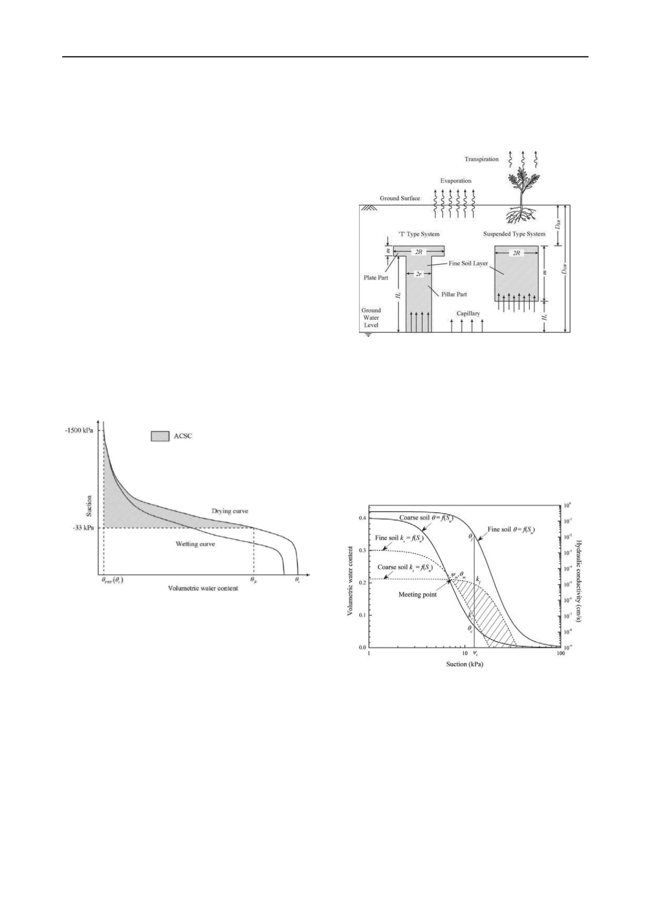
Figure 3 Soil water retention curve and unsaturated hydraulic
conductivity for finer soil and coarser soil
Theoretically, continuity of the pore water pressure requires
that the matric suction in the two layers must be equal at their
interface. As a result, the matric suction in the finer layer should
be equal to
ψ
e
(Figure 3). The volumetric water content in the
finer layer and coarser layer at
ψ
e
is noted as
θ
f
and
θ
c
respectively. Obviously,
θ
f
is larger than
θ
c
, which indicates the
finer layer has a higher capillary storage capacity (Equation 1).
However, the speed of the water flows from coarser layer into
finer layer is also influenced by hydraulic conductivity of both
layers. As shown in Figure 3, the two dash lines are unsaturated
hydraulic conductivity for finer and coarser soils respectively.
Two areas are formed by these two dash lines. One of these
areas is when the hydraulic conductivity of coarser soil is larger
than that of finer layer. On the opposite, the other area is when
the hydraulic conductivity of coarser soil is smaller than that of
finer layer. Therefore,
k
f
and
k
c
is corresponded to the hydraulic


