639
Technical Committee 102 /
Comité technique 102
considerations based on the results of the large numbers of in-
situ and laboratory tests. The resultant geotechnical engineering
map and the soil constants of each layers as characteristic values
are summarized in Figure 5 and Table 1, in which the soil
constants are mainly obtained by the standared consolidation
and triaxial undrained and drained compression tests. 3) Full-
scale pile load tests are conducted to confirm the validity of the
predicting method used for foundation design. The possibility of
reducing the safety factor for design to 2.5 from 3.0 is
considered through the geotechnical point of view based on the
field investigations, laboratory test results and the accuracy of
the predicting method with full scale pile load tests.
4 EVALUATION OF VERTICAL BEARING CAPACITY
OF DRIVEN PILES
4.1
Basic idea
Specification for Highway Bridge gives a following equation as
an estimating method of the ultimate pile bearing capacity based
on the results of the field and laboratory investigations (JRA,
1996):
Aq fLU R
d i i
u
(1)
Where R
u
: ultimate bearing capacity of pile, A: pile tip area, q
d
:
pile end bearing capacity, U: pile circumference, L
i
: thickness in
each layer, f
i
: maximum skin friction of pile. The first and
second terms are related to the skin friction of pile and pile-tip
bearing capacity, respectively. However, the main part of the
vertical bearing capacity of a pile is often mobilized from the
skin friction in practical designs within the limits of allowable
displacement, because relatively large displacements are needed
to mobilize the end bearing capacity. In addition, as a normal
open-end pile is used as a type of pile foundation, the end
bearing capacity strongly depends on the degree of the blockade
effect and thus the precise prediction of the end bearing capacity
was considered to be quite difficult. Then, as shown in Figure 6,
the skin friction mobilized through the internal face of the pile
under the bearing stratum was assumed as the equivalent end
bearing capacity in the design. Therefore, the second term q
d
A
is expressed as U
Lf
i
.
Skin friction
mobilized
Steel pile with diameters of 1m
Bearing stratum
Penetration
depth
L
Skin Friction mobilized here
is assumed as pile-tip resistance
Figure 6. Basic idea of pile bearing capacity
4.2
Evaluation of skin friction
4.2.1
Basic equation
The following basic equation is therefore used for calculating
the skin friction of piles which is determined as the sum of pile
to soil adhesion and friction components:
'
'
'
tan
h
c f
(2)
c’
and
'
are the adhesion and friction parameters between pile
and soil, and
'
h
is the effective lateral stress acting on the pile.
4.2.2
Soil constants as characteristic values
An idea that the adhesion between pile and soils is roughly
equal to the apparent cohesion of soils c’ is widely used for a
practical design. It is mentioned that the applicability of this
idea is effective, irrespective of type of soils such as clay and
sand (e.g. Tomlinson 1980). Therefore, c’
in eq. (4) was
assumed to be equal to the apparent cohesion c’ of soils. In
practical design, the axial pile capacity is estimated for the
settlements of approximately 10% of the pile diameter. The
10% settlements usually exceed those for mobilizing the
maximum skin friction of pile. Further, when considering that
the mobilized mechanism of skin friction between pile and soils
surrounding the pile, it is reasonable to use the friction angles at
the critical state corresponding to sufficiently large
displacement
’
cv
as
’
(Yasufuku et al. 1997). Here
’
is
assumed to be conservatively two-third of
’.
’
is thus given
by
'
3
2 '
(3)
where,
’: effective friction angle at peak strength state.
4.2.3
Coefficient of lateral effective stress K
The mobilization of the skin friction is dependent on the lateral
effective stress
'
h
and thus in turn is dependent on the
overburden pressure
'
v
. When considering
'
h
is given by
, Eq.(2) is rewritten by
v
K
'
'
'
'
tan
v
K c f
(4)
K is a coefficient of lateral effective stress and
’
v
is vertical
effective stress. The coefficient of lateral effective stress K was
estimated from the previous research findings related to the K
0
-
value. K-values in Pleistocene clayey layers were determined by
the following equation (Mayne and Kulhawy, 1982).
'
sin
'
sin 1
OCR
K
(5)
where, OCR is over-consolidation ratio defined as the ratio of
the consolidation yield stress p
c
to the overburden pressure
'
v
.
Values of OCR,
’ in average and the calculated K-values in
Eq.(5) are measured against elevation. We can say that applying
this equation into the Pleistocene clayey layers, most of K-
values became more than 1.0. Based on the experimental
evidence, K-value for design was decided as 1.0, irrespective of
type of Pleistocene layers. Thus, the presented model for
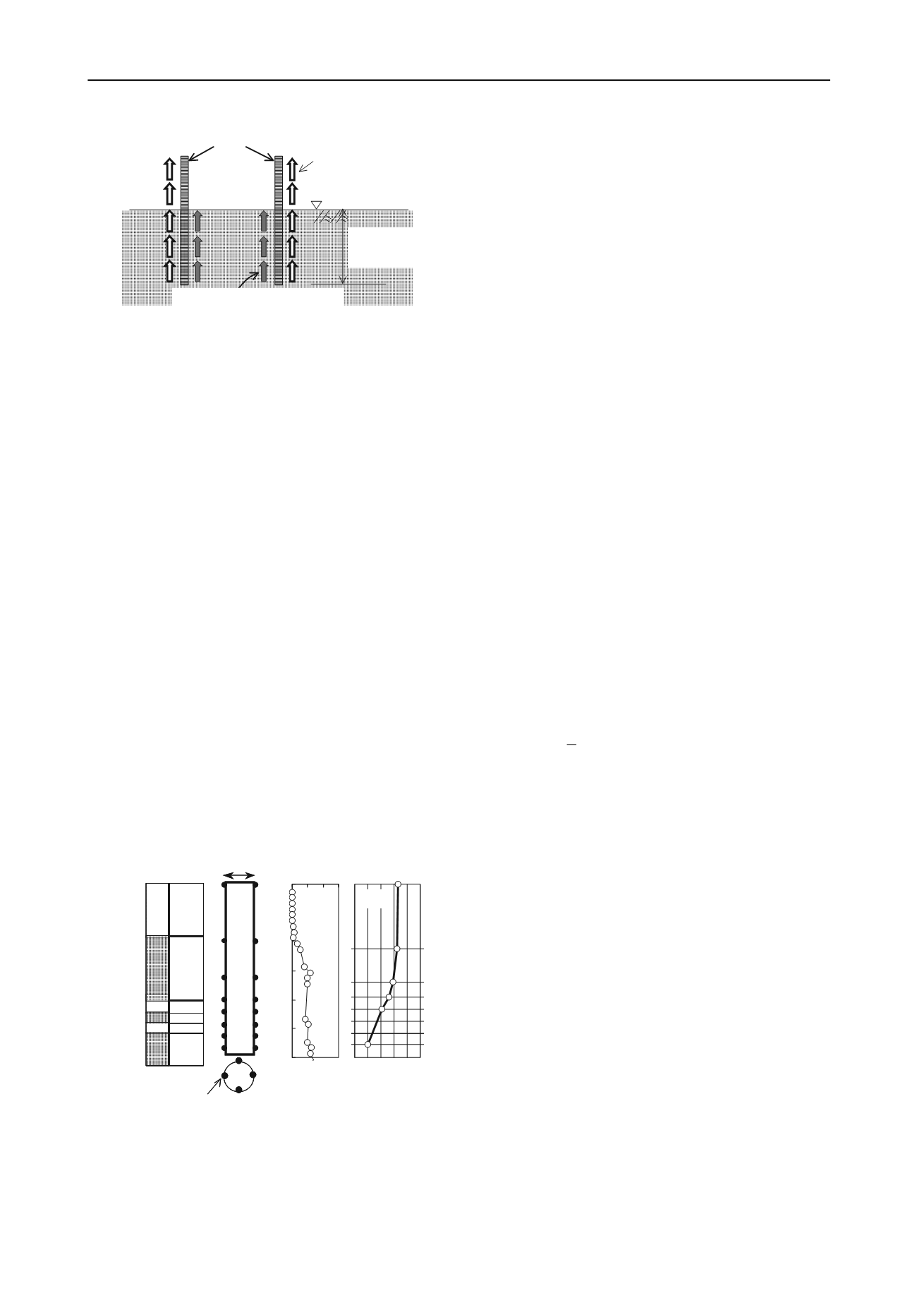
1.0m
Driven Pile (L=29m)
P12 site
DLs
DLs
Acl
(a)
Depth z (m)
0
5
10
15
20
25
30
DLc
DLc
DLs
Strain
gage (b)
S1
S2
S3
S4
S5
S6
S7
S8
0 2 4 6 8 10
Axial force
(MN)
(d)
0
5
10
15
20
25
30
0 20 40 60
N-Values
Depth (m)
(c)
(a)
Figure 7. Soil profile, N-values and measured axial force in pile
load test at P12 site
evaluating the vertical bearing capacity is expressed as
i
i i
u
Lf U fLU R
(6)


