638
Proceedings of the 18
th
International Conference on Soil Mechanics and Geotechnical Engineering, Paris 2013
T
0
-1
-2
-3
-4
-5
-6
-7
-8
-9
Sch
Sch
Ac
Ac
Ac
DLc
DLc
Schw Ttc
Ttc
DLs
DUs
DUc
DLs
DLc
TP
0
-10
-20
-30
-40
-50
-60
-70
-80
-90
(c) 1994-95
P22
A irport area
Sea area
Land area
Elevation (m)
A2
P12
P1
Unconformity
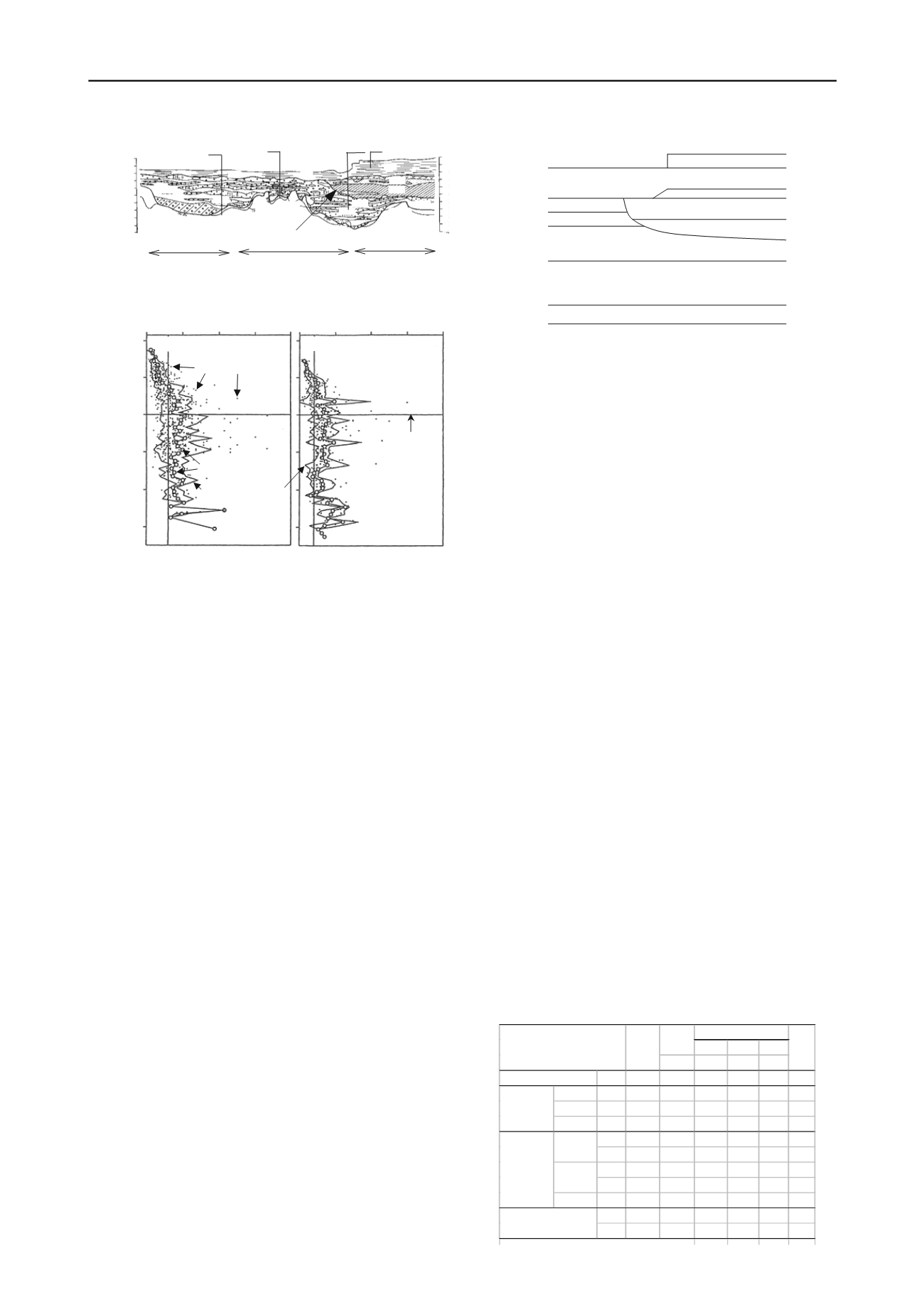
Figure 3. Final geotechnical engineering profile obtained
for New-Kitakyushu airport. As shown in this figure, the field
and laboratory investigations and the engineering design are
conducted based on the clear policy, which includes that:
1) The strong collaboration between geotechnical investigators
and designers should be made for a rational design and
construction in pile foundations.
2) The design parameters should be determined based on the
geotechnical considerations, which reflect the results obtained
from the geotechnical investigations and laboratory soil tests.
The model for estimating the bearing capacity of piles in design
should be based on the geotechnical considerations.
3) A rational bearing stratum should be carefully selected based
on the geological and geotechnical investigations.
4) The predicted performance in design should be checked by a
full-scale model tests as much as possible. The results are
reflected to the reduction of factor of safety for design.
Such policy seems to be strongly linked with the
performance based design, which may become the mainstream
in foundation design near future.
3 GEOTECHNICAL ENGINEERING MAP FOR DESIGN
REFLECTED THE SOIL PROPERTY
3.1
Geological profile with increases of site investigation
Figure 3 shows the final geotechnical engineering profile
mainly by the field investigations from 1992 to 1995, which
covers the land, sea and airport areas. Figure 3 was drawn by
adding the boring data in each pier of the access road, where the
total number of borings became more than 65 with 3500m in
total length, and the geological investigations on the diatom
earth and also volcanic ash deposit with the results of the
seismic exploration. The boring densities of each area in 1992,
1993 and 1995 are roughly 350m, 180m and 70m respectively.
It is judged that the geotechnical engineering profile becomes
more precise with the increasing boring density and quality of
in-situ investigations. The accuracy of geotechnical
investigations is believed to lead to the economical and rational
design and construction, even if the percentage of investigation
cost to the total one might be somewhat increased (see Table 2).
Figure 3 clarified that 1) the investigated ground consists of
alluvial clayey layers with 7-9m thickness and Pleistocene
layers laminated by sandy and clayey soils with 20-60m
thickness below the alluvial layers and also weathered
crystalline schist as the base layer. The corresponding ground is
therefore roughly divided into 3 layers. 2) The undulation of
base layer is extremely high in which the difference becomes
more than 45m. 3) The structure of Pleistocene layers is
complicated and the continuities in horizontal direction are not
so clear, and so the lens shape layers are found here and there.
4) The surface of unconformity in Pleistocene layers is clearly
found from sea area to airport area of which inclination is about
15 degrees in the longitudinal direction.
Embankment
Ac
DLs
1
DLc
1
DLs
2-5
DLc
2-6
Sch
DUs
DUc
Dutf
Figure 5. Model geotechnical engineering map for design
3.2
Model geotechnical engineering map for design
0 50
a) DLs layer
150 200 0 50 100 150 200
-10
-20
-30
-40
-50
-60
30
20
b) DLc layer
Evelation,T.P.
100
Bearing stratum
Measured N-values
Averaged N-values
Range of dispersion
N-blow values
N-blow values
Figure 4. Distribution of N-values in DL layer against depth
When determining a good bearing stratum for pile foundation,
Japanese design code by Japan Road Association recommends
that the N-values of sandy or sand-gravel layers are grater than
30 blow counts, and also N-values of clayey layers are more
than 20. Figure 4
shows the characteristics of N-values in
Pleistocene sandy and clayey layers obtained from the SPT. The
N-values of both layers tend to become more than 30 in average
when the depth is roughly deeper than 30m T.P. level. Based on
the results, the following guideline for pile foundation design
was determined such that: 1) The layer at 30m T.P level was
judged as an effective bearing stratum for driving the pile
foundation. A steel pipe sheet-pile foundation was selected as a
type of pile foundation in this project, where, all of pile tips are
set up in Pleistocene laminated ground at around 30m T.P.
levels. 2) As shown in Figures 3 and 4, the scatters of N-values
seems not to be small and also it is not easier to distinguish
from the sandy and clayey layers from N-values obtained
because the site consists of the complicated laminated sandy
and clayey layers. In this circumstances, the uniform and
empirical method based on the N-values is not rational and
precise to evaluate the pile bearing capacity. Thus, a method for
evaluating the pile vertical bearing capacity should be
introduced together with a proper geotechnical engineering map
for foundation design, which is derived by geotechnical
Table 1. Soil constants of each layer
c'
'
'
cv
(tf/cm
3
) (tf/m
2
) (degs.) (degs.)
Ac
0.0
0.53 0.292 0.0
33.0 1
Volucanic
Dutf 11.0
0.66 0.6 30.0
33.7 1-6
Sandy DUs 30.4
0.90 0.0 37.0
34.6 1-2
Clayey DUc 0.0
0.53 8.1 24.0
36.9 1-6
DLs
1
17.0
0.90 2.6 35.4
35.7 1-2
DLs
2-5
40.0
0.53 5.5 32.6
35.7 1-2
DLc
1
27.0
0.94 2.6 34.8
35.5 2-8
DLc
2-6
32.4
0.97 4.4 29.6
36.4 2-8
Gravel DLg 47.5
0.99 0.0 36.0
36.0 1
Sch-w 29.7
0.90 5.7 22.7
-
1
Sch 98.3
0.90 5.7 22.7
-
1
* OCR i t
l d d t
th d th
Clayey
Metamorphic rocks
OCR*
'
Sandy
N-value
Strength parameters
Alluvial clay
Pleistocene
(Upper)
Pleistocene
(Lower)


