450
Proceedings of the 18
th
International Conference on Soil Mechanics and Geotechnical Engineering, Paris 2013
water pressures u
dst;d
. Equation (2) refers the context to the flow
force S
dst;d
and the buoyancy weight G’
stb;d
and therefore to the
effective stress.
The following additional considerations of how to make
assumptions and define the boundary conditions for hydraulic
heave stability analysis and their interpretations are given in
DIN 1054:2010. For example, in flow around an excavation
wall conform to Terzaghi’s approach the reference volume can
be taken into account as a rectangle with a width of half of the
wall embedment depth. The hydraulic impact may be
differentiated on the basis of the soil type. Accordingly, the
partial safety factors can be distinguished for soils with flow
unfavorable or favorable characteristics. For at least stiff
cohesive soils the consideration of cohesion or tensile strength
as a material-specific parameter is permitted, if special expertise
and experience are available.
In particular, the reference to a possible consideration of
additional material specific strength properties indicates that the
valid approach lead to a conservative interpretation of the
relevant boundary conditions. Thus, according to the current
experience the approach is suitable especially for non-cohesive
soils. The existing shear strength of cohesive soils is neglected.
3 EXPERIMENTAL ANALYSIS
3.1 Visual failure state determination
The valid failure mechanism of cohesive soils is not so far
comprehensively analysed. Therefore experiments were carried
out to describe the structural failure during a hydraulic heave in
cohesive soils on the basis of a visual identification (Wudtke
and Witt 2006). The experimental setup and procedure rebuild
the water flow around a pit wall. The dividing wall was fixed on
frame sides.
The following questions were examined by the experiments:
- Which sequence of events can be characterized as the most
important attribute of hydraulic heave in cohesive soils?
- What phenomena are announcing the limit state?
- How the hydraulic decomposition of a cohesive soil can be
described?
- Where does the initial damage occur?
Table 1. Failure sequence during hydraulic heave in cohesive soils
Wudtke 2013)
(
Phase
Description
- water content increase,
- development of an initial crack with
origin at the foot of the dividing wall
- continuing pore widening,
- heaving of the downstream surface,
- development of a deep-lying fracture
- continuous crack initiation and closure;
- continuing heaving,
- locally limited decomposition of the soil
structure, dissection of the soil into
aggregates
Failure sequence
- continuing rapidly increasing elevation of
the soil surface,
- sudden failure as hydraulic heave,
- local potential equalization, failure body
erosion
From visual observations it can be stated that the failure
sequence is characterized as pore widening effects, soil
structure destroying crack opening and closing followed by a
final failure of the downstream surface.
Relative to a real excavation pit, the decomposition of the
soil structure at the foot of the flow around pit wall leads to
changing hydraulic routeing and flow distribution in the soil.
Consequence of the changed hydraulic boundary conditions is
increasing hydraulic impacts at the excavation side of the pit
wall.
The type of failure sequence is independent of the shear
strength of the soil. The failure principle is subjected to the
availability of cohesion and tensile strength. The activation of
resistances is related to the shear strength of the soil and the
stress state.
For low-cohesive soils in the course of crack opening and
closing processes a comparatively small resistance is activated.
At the same time the influence of shearing increases. How much
the resistance can be mobilized depends on the stress state of
the reference volume and the hydraulic head difference. An
increase of the water content causes plasticity changes and is
therefore sensitive to the occurrence of the failure.
3.2 Critical hydraulic gradient
Conventional tensile strength tests show that the tensile strength
of cohesive soils decreases with increasing of water content.
Basically it can be noted that tensile strength is available only
for soils with at least stiff plastic consistency. In these tests due
to the mechanically induced sample destruction the
conventionally determined tensile strength is only partially
representative for the detected hydraulic induced loss of
structural integrity of cohesive soils, (Wudtke and Witt 2010).
The development of a new testing method was required to
identify adequately the hydraulic induced limit state condition.
Objective of the testing method is to identify and quantify for a
certain construction status valid critical hydraulic gradient i
crit
.
The parameter represents the hydraulic impact required for a
structure decomposition of the soil. There are three main
influences on the test results: 1 – representative stress state, 2 –
pore water pressure, 3 – soil water content. In contrast to
conventional testing methods the test method considers a
hydraulic effect as the driving force for specimen destruction.
(Wudtke 2013)
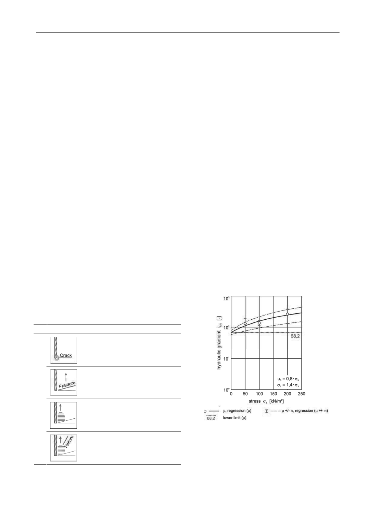
Figure 1. Stress-dependent critical hydraulic gradient, mean and
variation.
Examplary for an inorganic clay of medium plasticity (
’ =
23.5° und c’ = 13.7 kN/m²) the evaluation of the stress-
dependent development of i
crit
is shown in Figure 1. As
experimental conditions a principal stress ratio of
1
= 1.4 ·
3
at an initial pore water pressure of u
0
= 0.8 ·
3
were defined.
From the test results, the lowest limit value of i
crit
can be
determined for this kind of soil, i
crit
≥ 68.2 (Figure 1).
The experimental determination of the parameter i
crit
is basis for
defining the representative reference volume for calculating the


