2499
Technical Committee 211 /
Comité technique 211
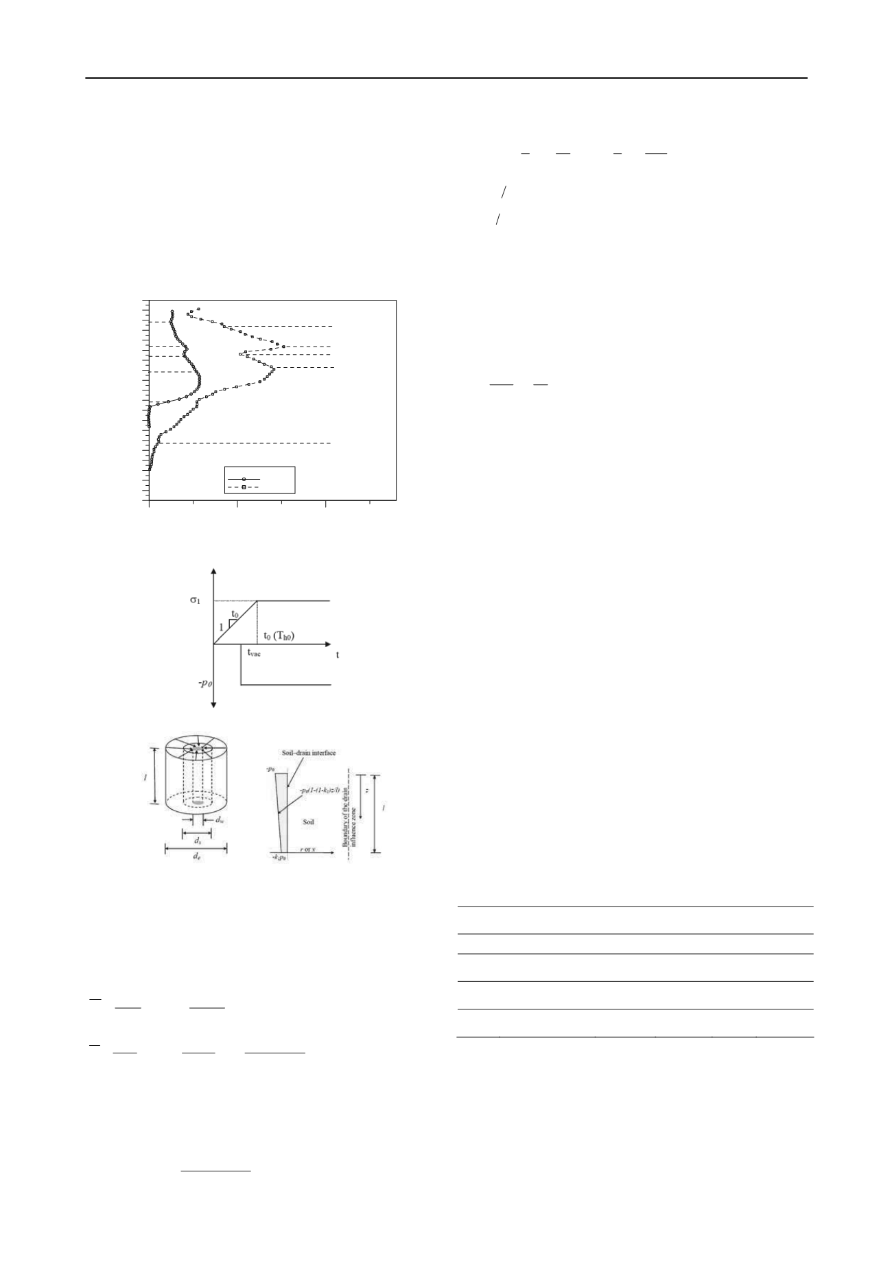
surcharge preloading. during embankment construction, the
surcharge fill is increased at a prescribed rate to reach the
desired height. therefore, the time-dependent loading due to the
filling would be more realistic than an instantaneous loading,
especially during the stages of embankment construction. in this
section, the embankment load is assumed to be a ramp loading:
i.e., the embankment load (
t
) increases linearly with time up to
a maximum value (
within time
t
0
and is constant thereafter
(fig. 4a). the vacuum is applied at
t=t
vac
. figure 4b shows the
unit cell adopted for analytical solutions with boundary
conditions (fig. 4c).
0
1
2
Lateral displacement/Total change in applied stress
(mm/kPa)
-30
-28
-26
-24
-22
-20
-18
-16
-14
-12
-10
-8
-6
-4
-2
0
2
4
6
8
10
Depth (m)
Section/Plate No.
VC1/MS28
WD3/MS27
Platform
Platform
Dredged mud
Dredged mud
HS
Holocene sand
UHC
Upper Holocene Clay
LHC
Lower HoloceneClay
figure 3. comparison of lateral displacements at the embankment toe in
vacuum and non-vacuum area after 400 days (indraratna et al. 2011)
(a)
(b)
(c)
figure 4. (a) time-dependent surcharge loading, (b) unit cell including
smear zone, and (c) boundary conditions with vacuum distribution (after
indraratna et al. 2011)
the excess pore pressure due to radial consolidation
considering smear effect under time-dependent surcharge can be
expressed by (indraratna et al. 2011):
0
1
2
0
2
0
8
exp 1
8
t t
for
d
tc
tc
d u
e
h
h
e
L
(1)
0
1
2
0
2
0
0
2
8
exp
8 exp 1
8
t t
for
d
t t c
d
tc
tc
d u
e
h
e
h
h
e
L
(2)
recently, indraratna et al. (2005) proposed that the excess
pore pressure dissipation due to vacuum pressure alone could be
determined from:
vac
vac
t t
u
,0
(3)
vac
e
vac
h
vac
t t
p
d
t t c
p
u
,
8
exp
0
2
0
(4)
2
3
2
4
3
ln
ln
l
q
k
s
k
k
s
n
w
h
s
h
(5)
w e
d d n
(6)
w s
dd s
(7)
where,
= the diameter of soil cylinder dewatered by a drain,
d
s
= the diameter of the smear zone, d
w
= the equivalent diameter
of the drain, k
s
= horizontal soil permeability in the smear zone
and q
w
= drain discharge capacity.
e
d
the excess pore pressure at a given time
t
can calculated
based on the equations (2) to (7). for normally consolidated
clay, the settlement (
) can now be determined by the following
equation:
i
c
e
HC
'
'
log
1
0
(8)
where,
= settlement at a given time,
C
c
= compression index,
and
H
= compressible soil thickness.
in order to calculate excess pore pressures and associated
settlements, equations (1)-(8) are employed using parameters in
table 2. for the completely remoulded dredged mud that was
reclaimed from the seabed and the Upper holocene sand the
ratio
k
h
/k
s
was assumed to be unity. for the upper and lower
holocene clay, the ratios of
k
h
/k
s
and
d
s
/d
w
were 2 and 3,
respectively, in accordance with the laboratory obsevrvation
decribed by indraratna and redana (1998).
the embankment load was applied according to a staged
construction (unit weight of 20 kn/m
3
). settlement and
associated excess pore pressure predictions were calculated at
the embankment centreline using eqs. 1-8. it is noted that, at the
beginning of each subsequent stage, the initial in-situ effective
stress was calculated based on the final degree of consolidation
of the previous stage. in vacuum areas, a suction pressure of 65
kpa was employed.
figures 5 and 6 present the predicted settlement and
associated excess pore pressure with the measured data in areas
Wd1 and Vc1, where the total applied load (vacuum and
surcharge =120-130kpa) and clay thickness (20-23m) are
comparable. overall, the comparisons between prediction and
field observation show that the settlement and associated pore
water pressure can be predicted very well. in vacuum areas, the
degree of consolidation was more than 90% after 13 months,
whereas that in the non-vacuum area was less than 85%. this
confirms that, at a given time, the vacuum combined preloading
would speed up consolidation compared to a surcharge
preloading alone. this is because in non-vacuum areas, a staged
embankment construction had to be adopted to avoid any
undrained failure in the remoulded dredged layer.
table 2. soil properties for each layer
Soil
layer Soil type
Cc/(1+e
0
)
c
h
(m
2
/yr)
k
h
/k
s
s=d
s
/d
w
1
dredged mud
0.235
1
1
1
2
Upper holocene
sand
0.01
5
1
1
3
Upper holocene
clay
0.18
2
2
3
4
lower
holocene clay
0.2
1.9
2
3


