2503
Technical Committee 211 /
Comité technique 211
characterized as having ll=50~60, pl=20~30, pi =20~30,
nmc=20~35%. according to Unified soil classification
system (Uscs), the soil in this layer is mostly plastic-silty clay
of low plasticity (cl), though a few samples were found to be
clay of high plasticity (ch). on the Uscs chart, the data points
lie just above a-line. the dry unit weight varied in the range of
13~15 kn/m
3
and the range of void ratio was 0.80~1.20. the
variation of these properties can be seen from figure 3. the
layer also has some organic content is about 1.4~4.0%. the
values of the coefficient of consolidation in the vertical
direction, c
v
were mostly within 3.1 to 25.2 m
2
/year and at
some location as low as 0.79 m
2
/year.
4 desiGn of GroUnd improVement method
it was decided by cpa, that the project will be carried out by
local contractors. therefore, capacity, experience, equipments
etc. of local contractors were to be considered in the design of
the yard. furthermore, ground improvement was to be
completed for the entire project site within one year. hence, the
area was divided into four blocks and time for improvement for
each block was 3 months. an area adjacent to the north
boundary of the site was earlier developed for similar purpose,
by a foreign contractor, where dynamic temping was used for
ground improvement and interlocking block pavement was
made. to keep similarity with the earlier part, interlocking
block pavement was decided for this yard too.
the presence of very soft to medium stiff silty clay at
various locations within the site indicated strong possibility of
substantial total and differential settlement unless effective
measures for improvement of sub-soil are undertaken before the
construction of pavement for the container Yard. therefore,
effective measures for improvement of sub-soil before the
construction of pavement were considered essential in order to
avoid/minimize future problems.
the necessity and extent of the ground improvement
measures are judged with an objective to reduce the differential
settlement and maintenance operations considering the
maximum load from stacking of containers on the entire area
(i.e. p= 52 kn/m
2
). it should be understood that a solution, for
which there will be no future settlement, will lead to high cost
and time for completion and thus may not be practical. the load
on the rtG tracks from the gantry is estimated to be 77.5
kn/m
2
. the extent of improvement and design of pavement
system at the site is targeted to keep maintenance option with
minimal disruption. for rtG and rmG tracks and other
facilities, suitable deep/shallow foundations will be considered
so that they do not undergo relative settlement with respect to
jetty top.
five alternatives, that appeared to be feasible for local
contractors, were assessed. these are- (i) preloading (ii) sand
drain with surcharge (iii) pVd with surcharge and (iv) dynamic
temping and (v) soft pocket identification, removal and
compacted backfilling. table 1 presents the comparison of cost
and completion time for different methods. Both time and cost
depends to some extent on the number of equipments mobilized
and source of material, particularly the surcharge (max. 5 m of
soil considered). considering the capacity of local contractors
minimal engagement of equipments and dredge sand from the
Karnaphuli river were considered.
though dynamic
temping/compaction appeared to be very prospective in terms of
time and cost, it posed the risk of damaging the adjacent yard
and structures. finally, pVd with surcharge was adopted as the
ground improvement measures, mainly because of reduced time
in pVd driving compared to sand drain installation, though
pVd is an imported material. also this method was considered
advantageous over other methods in bringing the clay layer to a
state where differential settlement potential will be reduced as it
will automatically take care of soft zones and bring the soft and
stiff zones to closer soil properties in terms of deformation and
strength.
since, from e~log(p) curves, most of the samples of the
upper clay layer was found to be normally consolidated, the
total consolidation settlement under the working loads (52 kpa)
without improvement was calculated using s
c
=
e.h,
e=c
c
/(1+e
0
)log(
p+p'
0
)/p'
0
and p'
0
=
'h where, e
0
= initial
void ratio, p'
0
= effective past maximum overburden pressure,
'=effective unit weight of soil, h=thickness of the compressible
layer. the estimated settlement for different borehole locations
varied from about 140 mm to 570 mm. this variation is due to
difference in e
0
, c
c
and layer thickness. in these estimations,
p
is calculated as
p =
0
[1-{1+(r/z)
2
}
-1.5
] where
0
=intensity of
stress applied on the surface, r = radius of the loaded area,
p=increase in stress at depth z from the centre of the loaded
area. this expression for
p is obtained by integration of
Boussinesque's equation that gives the stress at a point within a
semi-infinite, homogeneous, isotropic, weightless, elastic half-
space for a point load on the surface (Bowels,1988). estimated
time to achieve this consolidation (Uav
≈
99%) varied from
about 50 days to more than 700 days for different borehole
locations. the time was determined using terzaghi's one
dimensional consolidation theory with double drainage and
constant initial pore pressure distribution using the equations
(das, 1983):
m
0m
tm
2
av
v2
e
m
2
1 U
,
2h
tvc
vt
and
1 2m
2
π
m
it was intended to apply a surcharge with pVd such that a
maximum of 25 mm of total settlement remains to occur in
future under the working loads expecting a differential
settlement of not more than 12 mm. estimation of required time
to achieve this level of consolidation was made considering
both vertical and radial drainage (carillo,1942) as U=1-(1-
U
v
)(1-U
r
) where U
v
and U
r
are the average degree of
consolidation respectively for vertical and radial drainage. the
average degree of consolidation for radial drainage was
calculated using the following as
) 8 (
1
m
rT
r
e
U
where
2
e
vr
r
d
tC T
S
n
S n
k
k
n
S
S
n
S n
n m
s
h
ln
4 4
3
ln
2
2 2
2
2
2 2
2
w
e
d
d
n
and
w
s
d
d
S
the equivalent diameter of pVd was calculated following
hansbo (1979) as
)
(2
t b
d
w
where, b is the width and t is the thickness of pVd. considering
smear effect s was chosen between 1.0 and 1.2. the effective
diameter of soil column around the pVd was taken as d
e
=1.06s,
s=pVd spacing in triangular pattern.
for all the calculations horizontal permeability is taken as
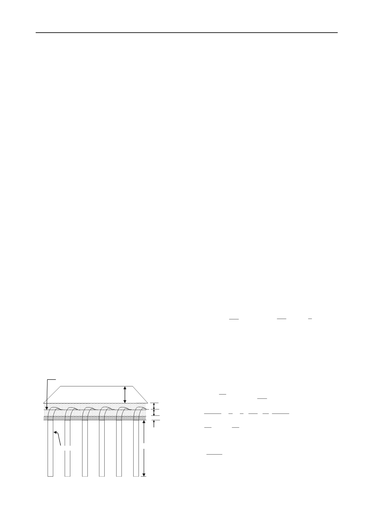
figure 4 details of the ground improvement work.
surcharge, 5m of soil
pVd
200 mm
5 m
Working surface for pVd installation
300 mm
150 mm


