2487
Technical Committee 211 /
Comité technique 211
4
ANALYSIS OF PILE CAPACITY
4.1 Total stress approach (α Method)
The so-called alpha method is a most common method to
calculate shaft resistance in total stress approach, which
correlates the shaft resistance, r
s
, to the undrained shear strength
of the clay, Su, via an adhesion reduction coefficient, α, as the
undrained shear strength of the soil increased:
r
s
= αS
u
(1)
For field CPTU tests, Lunne et al. (1985) proposed a method
to indirectly estimate the Su versus corrected cone resistance
(qt) as:
S
u
= (qt – σ
v0
)/Nkt
(2)
Where, Nkt is known as an empirical cone factor and σ
v0
is
the total overburden stress.
The records of undrained shear strength from the field vane test
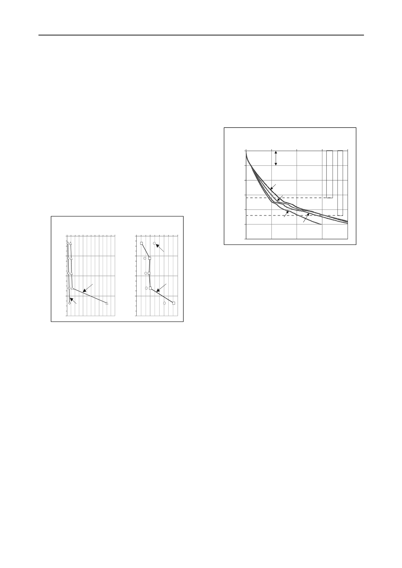
are substituted to Eq. (2) to determine Nkt as shown in Figure 7.
Figure 7. Correlation between cone stress and field vane
strength
To improve total stress approach, Randolph and Murphy
(1985) considered ratio of the undrained strength to the
effective overburden stress, σ’
v0
(stress history) and proposed a
reduction coefficient incorporated into the API 1987 edition
(excluding the effects of the pile length) as:
α = 0.5(S
u
/σ’
v0
)
-0.50
for (S
u
/σ’
v0
) ≤ 1
(3a)
α = 0.5(S
u
/σ’
v0
)
-0.25
for (S
u
/σ’
v0
) > 1
(3b)
The effects of the pile slenderness (ratio of the embedment pile
length, L, to the pile width, B) also were considered by Murff
(1980), Kraft et al. (1981), Semple and Rigden(1984), Randolph
and Murphy (1985). The unit shaft resistance proposed from
two alternative combinations of undrained shear strength and
effective stress was refined in the API 1993 edition as shown in
Eq. (4) and (5).
r
s
= 0.5(S
u
)
0.50
(σ’
v0
)
0.50
(4)
r
s
= 0.5(S
u
)
0.75
(σ’
v0
)
0.25
(5)
Kolk and van der Velde (1996) suggested an updated version
incorporated directly length effects and the unit shaft resistance
was determined in Eq. (6):
r
s
= 0.55(S
u
)
0.7
(σ’
v0
)
0.3
(40B/L)
0.2
(6)
The Nkt values in Figure 7 determined correlation between cone
stresses and field vane strengths are used to determine the Su of
CPTU test and calculate the unit shaft resistance according to
Eq. 1 and Eqs. 4 - 6.
The results are plotted in Figure 8 versus the accumulated unit
shaft resistance for the full dissipation of excess pore pressures.
For 5 m thick fill sand layer above the clay layer surface, the
effective stress analysis is applied with a coefficient β of 0.3
and indicates the bearing capacity of this layer is about 97 KN.
0
5
10
15
20
25
30
0
500
1,000 1,500 2,000
SHAFT RESISTANCE (KN)
DEPTH (m)
Eq. 1
Eq. 4
Eq. 6
Eq. 5
β = 0.3
P
I
L
E
2
2
m
P
I
L
E
1
6
m
Sand
Clay
Sandy silt and silt
4
8
12
16
20
0 30 60 90
S
u
(kPa) & N
kt
DEPTH (m)
N
kt
S
u
4
8
12
16
20
0 2,000 4,000 6,000
DEPTH (m)
q
t
&
σ
v0
(kPa)
q
t
σ
v0
Figure 8. The accumulated shaft resistances versus depth
1.1
Effective stress approach (β Method)
The effective stress approach for evaluating the pile capacity,
Burland (
1973
) developed a simple equation written as:
r
s
= Ktanδσ’
v0
= β σ’
v0
(7)
Where, K is the lateral earth-pressure coefficient, δ is the
constant volume friction angle, and β = Ktanδ is Bjerrum-
Burland coefficient.
Two direct CPTU methods typical of effective stress
approach are method of Eslami and Fellenius (1997) and
Takesue et al. (1998). In the Eslami and Fellenius CPTU
method, the cone stress is transferred to an apparent “effective”
cone stress, q
E
, by subtracting the measured pore pressure, U
2
,
from the measured total cone stress, q
t
, the unit shaft and toe
resistance is obtained from:
r
s
= C
s
q
E
(8)
Where,
C
s
is
the side correlation coefficient determined from
the soil profile chart
which uses both cone stress and sleeve
friction.
For method of Takesue et al. (1998), the unit pile shaft
resistance,
r
s
, is estimated from the measured sleeve friction,
fs
,
which is scaled up or down depending on the magnitude of the
measured excess porewater pressures during penetration,
ΔU
(ΔU = U
2
– U
0
)
. The data used to derive the correlation were
obtained from both bored and driven pile foundations in clays,
sands, and mixed ground conditions.
r
s
= f
s
(ΔU/1250+0.768) for ΔU<300 kPa (9a)
r
s
= f
s
(ΔU/200-0.5) for 300<ΔU<1,250 kPa (9b)
The results of the effective stress analysis are presented in
Figure 9.
For fill layer above clay surface, the analysis is made
the same as above total stress analysis.


