945
Technical Committee 104 /
Comité technique 104
laterally to a more rigid lateral/basal base by trajectories of the
major principal stress. Failure happened along the shear plane
generated by relative displacement. Because the undercut of a
steep slope generates more stress relief, the shear zone is bigger
with a wider shape at the top. While the shear zone of a mild
slope is smaller with a wider shape at the bottom. This
difference causes many failures of arches. Subsequent stacks of
arches can form in a mild slope until reaching the collapse of a
whole slope, while failure will happen aggressively for a steep
slope due to slope buckling without many local failures.
Characterization of each type of failure is different by means
of arching coefficients,
k
, based on theoretical mechanics and
validated by the results of the physical model test. Three values
of the coefficient are provided for (1) a strip arch with soil slip,
(2) a segmented arch with stable scarp and (3) a circular arch
with slope buckling. For a slope with no arching, the arching
coefficient is merely zero.
5 APPLICATIONS TO SITE CONDITIONS
Since bedding shear zone in the clay seam layer is considerably
thin, excessive pore water pressure can be dissipated in a short
time. The drained shear strength obtained from a constant-
volume direct shear test with measurement of vertical stress
change is considered applicable to the site condition (Ohta et al.
2010). Wangsa et al. (2012) and Pipatpongsa et al. (2011)
examined the mechanical properties of G1 green clay which is
associated with a bedding shear zone in Area 4.1. The residual
friction angles with zero cohesion-intercept obtained from
multi-stage reversal constant volume direct shear box test are
ranged from 12 to 17. Therefore, the minimum value of 12
was considered as a critical case. Moreover, consideration of
hydro-static pressure is required in engineering practice. Four
cases are considered below.
A) Failure width of passive arching slope in dry condition
sin tan cos
c
f
i
k
B
(3)
B) Failure width of passive arching slope in dry condition
with hydro-static pressure on bedding shear plane
sin 1
tan cos
c
f
w
i
k
B
(4)
C) Failure width of passive arching slope in fully saturated
condition with no hydro-static pressure on bedding shear
plane
1
sin tan cos
c
f
w
i
k
B
(5)
D) Failure width of passive arching slope in fully saturated
condition with hydro-static pressure on bedding shear
plane
1
sin 1
tan cos
c
f
w
w
i
k
B
(6)
As the last condition is the most critical case, Eq.(6) is
employed to determine the failure width in the implementation
at the site. Based on various laboratory and field experiments,
the material parameters (EGAT 1985, 1990, Khosravi et al.
2011 and Wangsa et al. 2012) are selected for the analysis as
summarized in Table 1. The contribution of the arching effect
can be evaluated by a factor of safety. The safety factor for a
two-dimensional slope (planar condition) is simply calculated
by Eq.(7) and Eq.(8) for dry and submerged conditions,
respectively. Based on Eq.(3) and Eq.(6), the factor of safety for
three-dimensional slopes (arching effect condition) can be
calculated by Eq.(9) and Eq.(10) for dry and submerged
conditions, respectively.
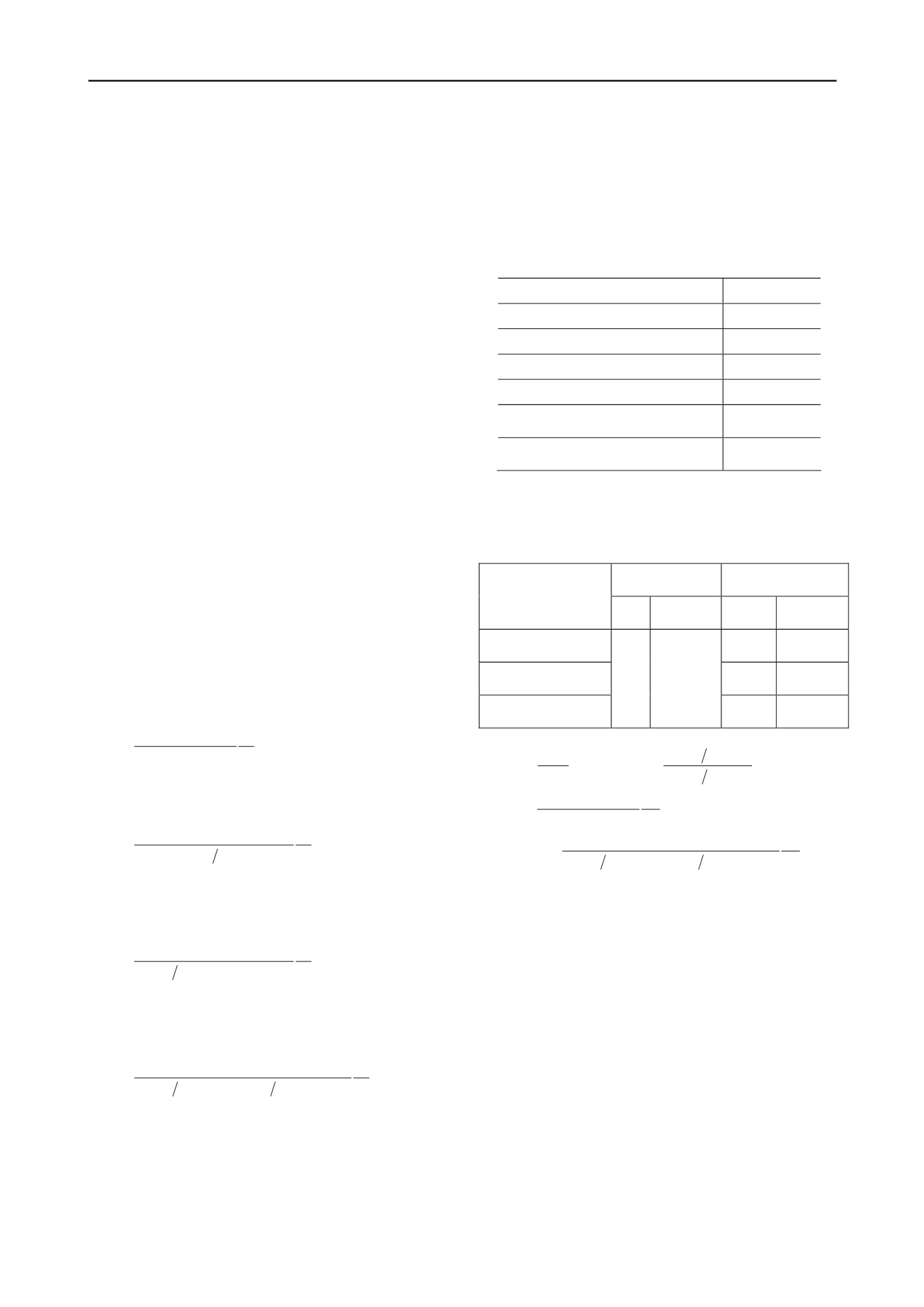
Table 1. Geometry and material parameters of the green clay seam and
hale required for calculating safety factor of the undercut slope.
s
Inclined slope,
18
o
Residual interface friction angle,
i
12
o
Bulk unit weight of shale,
19.12 kN/m
3
Unit weight of water,
w
9.81 kN/m
3
Residual UCS of shale,
cr
0.33 MPa
Peak UCS of shale,
cp
4.50 MPa
Designed UCS of shale,
cd
1 MPa
UCS =
unconfined compressive strength
Table 2. Calculated safety factors against a width 130 m for dry and
submerged conditions under two and three dimensions using residual,
peak and designed values of unconfined compressive strength of shale
ith an arching coefficient assigned to
k
2
=1.
w
2D
(planar
slope)
3D
(arching
effect)
Safety factor
d
ry
subme
rged
dry
submer
ged
Residual
rock
strength
1.2
0.4
Peak
rock
strength
16.
9
4.9
Designed
rock
strength
0
.6
0.2
3.8
1.1
2 ,
tan
tan
i
D dry
SF
,
2 ,
1
tan
1
tan
w
D submerged
w
SF
i
(7), (8)
3 ,
sin tan cos
c
D dry
i
k
SF
B
(9)
3 ,
1
sin 1
tan cos
c
D submerged
w
w
i
k
SF
B
(10)
Using the material parameters shown in Table 1, the safety
factor determined from Eqs.(7)
(10) are shown in Table 2. In
the calculation, the arching coefficient assigned to
k
2
=1 for mild
slopes with supporting ground for the maximum exposed width
130 m. Safety factors based on a planar condition for both dry
and submerged conditions are less than one which might
conclude that the slope cannot be undercut. However, an
arching effect allows a higher factor of safety; therefore, if the
shale above the clay seam has not been weathered into weak
soft rock, mining at Area 4.1 with the span of 130 m is possible.
The undercut span at Area 4.1 is varied as a function of the
unconfined compressive strength of the shale; thus, if the
unconfined compressive strength of shale on the slope could be
maintained at 1 MPa at the least, the undercut span of 130 m at
the clay seam level can be reached safely in a short term.
The width of Area 4.1 in the Mae Moh lignite mine is about
300 m and the length about 250 m along the pit wall. The total
depth of 33 m in this area for lignite mining was planned by
digging 3 benches with a height of 11 m each. According to
EGAT’s mining plan, Area 4.1 is divided into 2 stages of
excavation, namely stage 1 for 180 m and stage 2 for 120 m


