944
Proceedings of the 18
th
International Conference on Soil Mechanics and Geotechnical Engineering, Paris 2013
According to the full core drilling, which consists of up to 900
holes have been drilled in the Mae Moh mine during the period
1987
2005. The thickness of the bedding shear zone ranges
from 10 to 80 mm. About 40% of the bedding shear zone
comprises continuous layers of clay seam. In this study, the
targeted area is Area 4.1, shown in Fig.1. Its cross-section is
shown in Fig.2.
Potential failure plane
(Shearing zone, green clay)
Lignite layer
Unstable rock mass
Borehole NEI N29
(Depth: 50m)
A
A’
Figure 2. Cross-section A-A’ of Area 4.1 (Courtesy of EGAT)
Blockof moist Silica
sand No. 6
Position of block
before slippage
α
f
Figure 3. Slippage of the sand block along the lateral supports (after
Khosravi et al. 2012)
Side supports
Side supports
α
=40
o
T
=0.05m
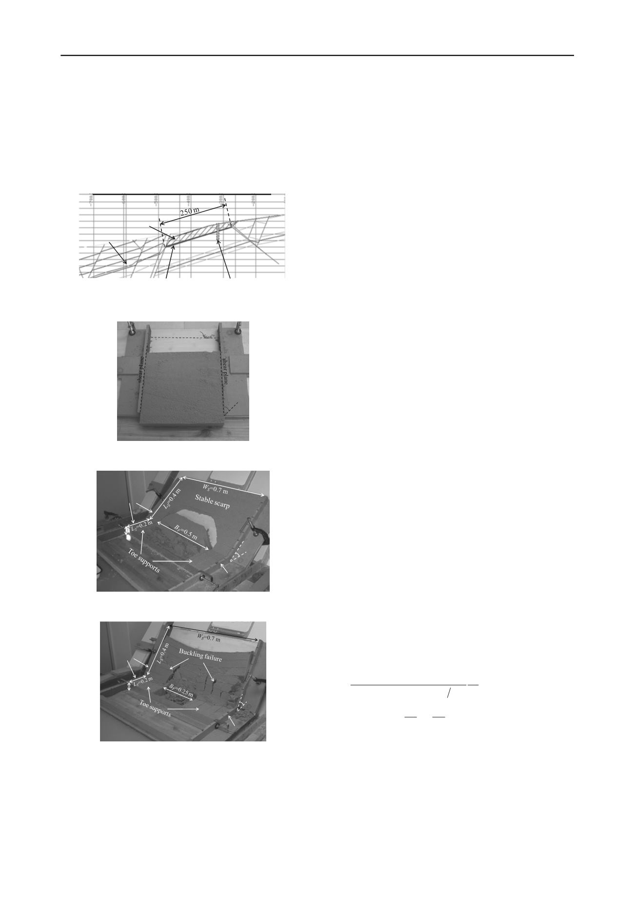
Figure 4 Arch-shaped failure in mild undercut slopes at the maximum
undercut span (after Khosravi et al. 2012)
Side supports
Side supports
α
=60
o
T
=0.05m
Figure 5. Buckling failure in steep undercut slopes at the maximum
undercut span (after Khosravi et al. 2012)
3 PHYSICAL MODEL
Khosravi et al. (2009, 2010, 2011) have conducted a series of
simple experiments using a block of compacted moist sand
confined by parallel rigid walls by varying thickness, width and
length. The inclined angle of the bedding plane was gradually
increased until the block started to slip (see Fig.3). Also, some
laboratory-scale undercut slope physical model tests were
conducted under both 1G and centrifugal acceleration fields.
The existence of passive arching effects in the slope models can
be confirmed by means of earth pressure recordings and image
processing techniques. In the undercut slopes, some parts of the
load are transferred from the yielding portion of the slopes to
the stiffer sides. The level of load transfer depends on the
stiffness and strength of the lateral supports. Two types of slope
failures can be expected: an arch-shaped failure (see Fig.4) in
the central part of the slope for the strong sides, and side
buckling (see Fig.5) leading to total failure of the slopes for the
weak sides. In addition, the performance of a counterweight
balance, which is considered a technique to stabilize undercut
slopes with weak sides, was demonstrated through a series of
physical models and confirmed that a wider undercut span in
front of the slope can be realized (Khosravi et al. 2012).
4 THEORETICAL BACKGROUND
In chemical engineering, a stable arch formed across the orifice
of a hopper causes difficulty in discharging of cohesive
material; therefore, determination of the minimum diameter
which destabilizes the arch action is required. On the other
hand, in mining engineering, a stable arch formed across a pit is
beneficial to the design of an undercut slope; therefore,
prediction of the maximum undercut width which does not
cause it to collapse is needed. Jenike’s (1961) model for arch
formation has laid the foundation for understanding the
behavior of a static system of cohesive materials confined by
hopper walls (Walker 1966 and Walters 1973). This study
extends a basic idealization of a stationary system used by
Jenike (1961) to the stability of a laterally confined rigid block
inclining on a stiff bedding plane. The following similar
assumptions were adopted in the present study with an
additional consideration of interface resistance: (a) the
resistance supporting the arch is characterized by unconfined
compressive strength, and (b) the load breaking the arch is due
to its own weight and to the force exerted by the material above
the arch. The mechanism involved and its implication on
instability can be explained in that if the load induced by weight
of the arch is greater than the unconfined compressive strength
and the interface resistance, the arch will collapse and therefore
the widest possible span or the failure width of block
B
f
of a
stable arch can be predicted.
The authors (Khosravi 2012) have recently developed
equations to describe the instability phenomena of undercut
slopes based on Jenike’s (1961) theory of cohesive arching in
hoppers, as shown in Eq.(1) which can be alternatively
expressed by Eq.(2) in terms of the inclined angle at failure
f
for a given span of undercut
B
.
sin tan cos
c
f
i
i
k
B
c T
(1)
1
sin
cos
i
c
f
i
c k
T B
i
(2)
where
α
: inclined angle,
T
: thickness of block,
i
: interface
friction angle,
c
i
: interface adhesion,
c
: unconfined
compressive strength,
: bulk unit weight,
: friction angle of
material,
k
: arching coefficients:
k
=0
no arching
k
1
=cos
strip arch with soil slip
k
2
=1
segmented arch with stable scarp
k
3
=4/π
circular arch with slope buckling
The arching effect is the ability of soil to transfer load


