1636
Proceedings of the 18
th
International Conference on Soil Mechanics and Geotechnical Engineering, Paris 2013
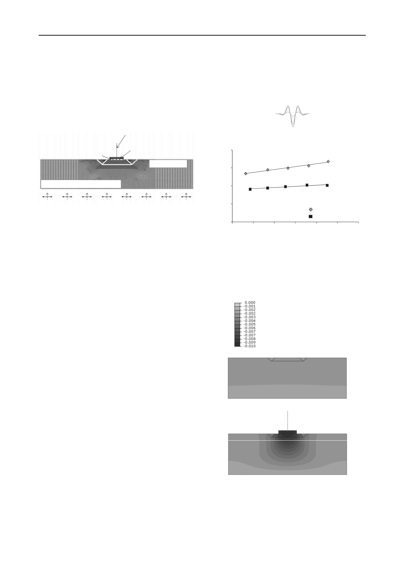
2 NUMERICAL METHODOLOGY
The problem is analyzed employing the finite element code
ABAQUS. The geometry and the key aspects of the model used
in the analyses are presented in Figure 2. Assuming plain strain
conditions, a representative “slice” of the soil–foundation–
structure system is examined, taking account of material (soil
and superstructure) and geometric (footing uplift, sliding, and
P–δ effects) nonlinearities.
Surroundingsoil:nonlinear4‐node elements
Foundation–soil
interface
Synthetic liners
Footing:
elastic4‐nodeelements
Pier:
nonlinearbeamelements
Figure 2. The finite element model used in the analyses: plain strain
conditions are assumed, considering material (soil and superstructure)
and geometrical (sliding, P-Δ phenomena) nonlinearities .
The soil is modeled with 4-noded continuum elements. The
soil behavior is modeled through a nonlinear constitutive model
with Von Mises failure criterion, nonlinear kinematic hardening
and associated plastic flow rule. The footing is modeled with
elastic 4-noded continuum elements with
E
= 30 GPa. Beam
elements are used for the pier, with their nonlinear behavior
being modeled with a kinematic hardening model (Gerolymos et
al., 2005), similar to that of the soil. Model parameters are
calibrated against moment–curvature relations of the reinforced
concrete pier, computed through section analysis utilizing the
XTRACT software (Imbsen & Assoc., 2004). The deck is
represented by a mass element, and the contact between the
different parts of the model (footing, embankment, wedges,
surrounding soil) is modeled with a special interface that allows
realistic simulation of possible sliding and detachment.
3 DYNAMIC RESPONSE OF THE ISOLATION SYSTEM
Initially, the in-soil isolation system is subjected to idealized
Ricker pulses of characteristic frequency
f
= 2 Hz and gradually
increasing maximum acceleration (0.1g to 0.5g). Both the fully
SSI problem as well as the free-field problem (i.e., ignoring the
presence of the superstructure) are analyzed.
In Figure 3 the response of the isolation system is presented
in terms of maximum acceleration at the top of the isolated
embankment with respect to the maximum acceleration at the
surface of the non isolated free-field (PGA), both in and without
the presence of the pier. Evidently, the effectiveness of the in-
soil isolation system depends on the presence of the
superstructure. Maximum acceleration at the top of the isolated
embankment does not exceed 0.2 g without the superstructure
on top. On the other hand, the presence of the pier leads to an
increase in the acceleration, which in this case ranges between
0.28 g and 0.33 g.
In Figure 4 the deformed mesh with superimposed
displacement contours, showing the deformation of the system
when in the presence of the pier and without it. The deformation
scale factor applied is deliberately large, in order to highlight
the difference between the two cases examined. Observe the
aforementioned increase in the acceleration that passes through
the isolation layer, which is due to its deformation by the
vertical pressures which are imposed by the weight of the pier.
As a result, the isolated embankment is forced to slide on a
curved surface, rather than a horizontal one. Consequently, the
acceleration that is required for slippage is increased
substantially, reducing the effectiveness of the isolation system.
Ricker
f = 2 Hz
a
max
= 0.1 ÷ 0.5 g
PGA
(g)
a
(g)
0
0.1
0.2
0.3
0.4
0.2
0.3
0.4
0.5
0.6
0.7
0.8
superstructure
free‐field
Figure 3. Maximum acceleration at the top of the isolated embankment
with respect to the maximum acceleration at the surface of the non
isolated free-field (PGA), with and without the presence of the pier. The
bedrock excitation is an idealized Ricker wavelet of characteristic
frequency
f
= 2 Hz, and gradually increasing maximum acceleration
(from 0.1g to 0.5g).
U
vert
(m)
Figure 4. Deformed mesh with superimposed vertical displacement
contours considering the superstructure on top of the isolated
embankment and without it. (deformation scale factor = 100).


