 
          1561
        
        
          Technical Committee 203 /


            Comité technique 203


          dense specimens have curves rising sharply as the number of
        
        
          cycles decreases; and (2) while the effect of relative density is
        
        
          very pronounced for Toyoura sand, the effect of relative density
        
        
          on pumice specimens appear to be not as remarkable.
        
        
          4.2


            Effect of confining pressure


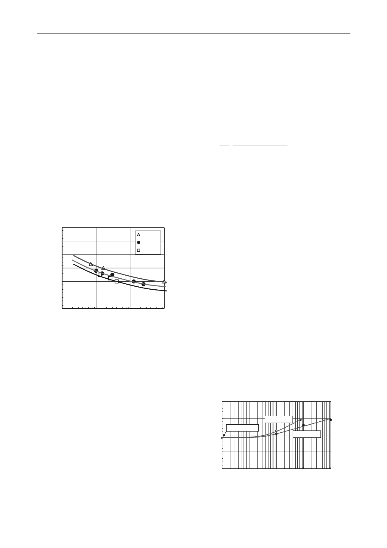
          Next, the influence of effective confining pressure on the
        
        
          liquefaction resistance of reconstituted pumice sands was
        
        
          investigated. For this purpose, dense pumice sand specimens
        
        
          (initial void ratio,


            e


            i


          =1.90-2.00) were subjected to three different
        
        
          levels of effective confining pressure,


            c


          ’=35, 100 and 500 kPa
        
        
          under different levels of cyclic shear stress ratio, CSR
        
        
          (=


            d


          /2


            c


          ’). Figure 3 illustrates the confining pressure
        
        
          dependency of liquefaction resistance for reconstituted pumice.
        
        
          It can be seen that the curves are almost parallel to each other,
        
        
          with the liquefaction resistance increasing as the confining
        
        
          pressure decreases, consistent with the observations made on
        
        
          natural sands (e.g., Rollins and Seed, 1988). The value of the
        
        
          correction factor for overburden stress


            K


          (CSR causing


            DA


          =5% in 15 cycles under any confining pressure normalised
        
        
          to the corresponding value of CSR at


            c


          ’=100 kPa) is equal to
        
        
          1.16 for


            c


          ’=35 kPa and 0.88 for


            c


          ’=500 kPa.  These values
        
        
          appear to coincide with those reported for reconstituted natural
        
        
          sands (e.g., Boulanger and Idriss, 2004).
        
        
          4.3


            Development of particle crushing during cyclic loading


          The level of particle crushing during undrained cyclic testing
        
        
          has been reported by Orense et al. (2012). They noted that under
        
        
          the confining pressures considered, pumice undergoes
        
        
          remarkable particle crushing when subjected to cyclic shear. As
        
        
          cyclic shearing and particle crushing occur, the soil structure is
        
        
          gradually stabilized, resulting in higher cyclic shear resistance,
        
        
          even exceeding that of Toyoura sand. The cyclic shearing and
        
        
          the associated particle breakage resulted in stable soil structure
        
        
          for both dense and loose cases, and therefore, the effect of
        
        
          density was not as remarkable when compared to the cyclic
        
        
          behaviour of Toyoura sand, a hard-grained sand.
        
        
          To elucidate further the development of particle crushing
        
        
          during a cyclic loading, a series of tests were performed such
        
        
          that the tests were terminated after a specified number of cycles
        
        
          afterwhich sieve analyses were performed. For these tests,
        
        
          virgin samples were used at each test. A confining pressure of


            c


          ’=100 kPa was considered, with the void ratio set at


            e


            i


          =1.90-
        
        
          2.00. For CSR=0.10, the sieve analyses were carried out: (1) on
        
        
          the virgin samples; (2) after the end of consolidation stage; (3)
        
        
          after


            N


          =10 cycles; (4) after


            N


          =100 cycles; and (5) after


            N


          =1000
        
        
          cycles. On the other hand, for CSR=0.20, sieving was done (1)
        
        
          after


            N


          =10 cycles; and (2) after


            N


          =83 cycles where initial
        
        
          liquefaction (pore pressure ratio,


            r


            u


          =100%) occurred.
        
        
          The grain size distributions of the specimens after the tests
        
        
          were determined. Particle crushing occurred, but with the level
        
        
          of CSR and the number of cycles applied, it was difficult to use
        
        
          the grading curves to make reasonable comparison. Instead, a
        
        
          method of evaluating particle crushing originally proposed by
        
        
          Miura and Yamanouchi (1971) was used which involves the
        
        
          quantification of the surface area of the particles. The specific
        
        
          surface of the particles was measured by first sieving the soil
        
        
          using 2.5 mm, 2.0 mm, 1.18 mm, 0.5 mm, 0.212 mm, 0.15 mm
        
        
          and 0.063 mm sieve sizes. For this range of particle sizes, the
        
        
          specific surface area (in mm
        
        
          2
        
        
          /mm
        
        
          3
        
        
          ) is calculated as:


            d


            ws


            m


            m


            G d


            d


            F S


          3
        
        
          2
        
        
          2/
        
        
          3/4
        
        
          2/
        
        
          4
        
        
          100
        
        
          (1)
        
        
          where


            d


            m


          =(


            d


          1
        
        
          .


            d


          2
        
        
          )
        
        
          0.5
        
        
          ,


            d


          1
        
        
          and


            d


          2
        
        
          are adjacent sieve sizes (e.g.,
        
        
          0.50mm and 0.212 mm),


            F


          is the % by weight retained on the
        
        
          sieve,


            G


            s


          is the specific gravity of the particles,


            w


          is the unit
        
        
          weight of water and


            d


          is the dry unit weight of the specimen.
        
        
          Figure 4 shows the development of the surface area


            S


          for the
        
        
          different tests described above. Firstly, it was observed that
        
        
          consolidation at 100 kPa effective confining pressure did not
        
        
          induce appreciable particle breakage to the pumice particles;
        
        
          however, the cyclic shearing did. Secondly, the degree of
        
        
          particle crushing increased with the amplitude of applied CSR.
        
        
          For the test with CSR=0.20, the increase in surface area during
        
        
          the initial stage of cyclic loading was small; however, as the
        
        
          liquefaction stage was reached (


            N


          =83), the surface area
        
        
          increased remarkably because large strains occurred with
        
        
          associated translation and rotation of particles causing the
        
        
          higher degree of crushing.  For CSR=0.10, the state of
        
        
          liquefaction did not occur even when


            N


          =1000 cycles. Particle
        
        
          breakage was more or less gradual, with almost linear variation
        
        
          with the logarithm of


            N.


          4.4


            Comparison between laboratory and field data


          Cone penetration tests (CPT) and seismic dilatometer tests
        
        
          (sDMT) were performed at the Mikkelsen Rd site and Carrs Rd
        
        
          site to supplement the undrained cyclic triaxial tests conducted
        
        
          on the undisturbed samples taken from these sites. The field
        
        
          tests were performed as near as possible to the sampling site.
        
        
          Correlations between the cyclic resistance obtained from the
        
        
          laboratory tests and the in-situ parameters were performed to
        
        
          confirm which method was appropriate for pumice. Note that
        
        
          undisturbed soil samples were obtained at three elevations at
        
        
          Mikkelsen Rd site, while samples from Carrs Rd site were taken
        
        
          only at a single depth; hence, emphasis is placed on the former.
        
        
          In addition, the results presented herein may be appropriate only
        
        
          for the two sites investigated and further tests are necessary to
        
        
          confirm their applicability to other pumiceous sites.
        
        
          0
        
        
          0.1
        
        
          0.2
        
        
          0.3
        
        
          0.4
        
        
          0.5
        
        
          0.6
        
        
          1
        
        
          10
        
        
          100
        
        
          1000
        
        
          C
        
        
          yclic
        
        
          S
        
        
          hearS
        
        
          tress
        
        
          R
        
        
          atio,C
        
        
          S
        
        
          R
        
        
          Number of cycles, N
        
        
          35 kPa
        
        
          100 kPa
        
        
          500 kPa
        
        
          Figure 3: Comparison of liquefaction resistance curves for reconstituted
        
        
          dense pumice sands under different


            c


          ’
        
        
          .
        
        
          In the comparison, the liquefaction resistance of the
        
        
          undisturbed samples is specified in terms of the magnitude of
        
        
          80
        
        
          85
        
        
          90
        
        
          95
        
        
          100
        
        
          0
        
        
          1
        
        
          10
        
        
          100
        
        
          1000
        
        
          S
        
        
          urface
        
        
          area,S
        
        
          (m
        
        
          m
        
        
          2
        
        
          /m
        
        
          m
        
        
          3
        
        
          )
        
        
          No. of cycles, N
        
        
          �
        
        
          d
        
        
          /2
        
        
          �
        
        
          c
        
        
          ’=0.20
        
        
          �
        
        
          d
        
        
          /2
        
        
          �
        
        
          c
        
        
          ’=0.10
        
        
          Consolidation
        
        
          Figure 4. Relationships between specific surface area and number of
        
        
          cycles during cyclic undrained tests.