1372
Proceedings of the 18
th
International Conference on Soil Mechanics and Geotechnical Engineering, Paris 2013
Figure 7. Photo of retaining wall after final excavation phase, after
backfill for piling rig
5 MONITORING
An extensive monitoring program was set up to measure the
vertical and horizontal displacements of the wall during the
different excavation stages. Specially instrumented beams were
placed in the columns to measure deformations and strains in
the reinforcement (L. De Vos, 2013). These reinforcement
beams were exceptionally put into place in one piece and
installed when the train tracks were out of service.
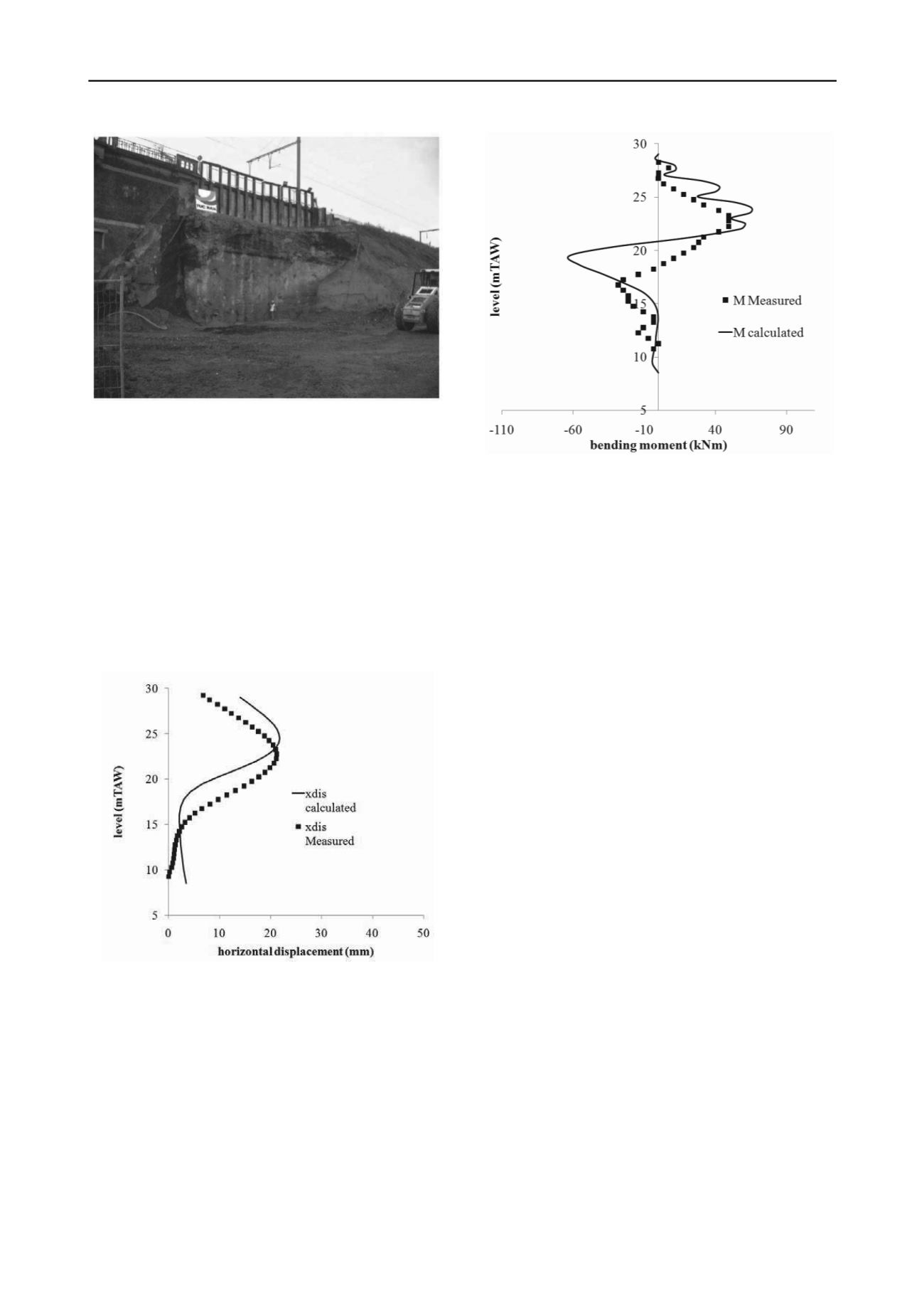
Figure 9. Comparison between calculated and measured (derived)
bending moments.
6 CONCLUSION
The measurements lie in close approximation to the
calculated values. Figure 8 compares the measured and
calculated horizontal displacements of the wall. Displacements
are measured with an inclinometer, in which the bottom
measurement is considered to remain unchanged.
For the construction of a retaining wall adjacent to railway
tracks, the restrictions in available space and allowable height in
machinery led to a combined retaining wall consisting of a
small Berliner wall and deep VHP jet grout wall. The design
was based on different in situ and laboratory tests, and was
checked through monitoring of the excavation and performing
preliminary true scale measurements. The execution of jet grout
piles turned out to be difficult due to peat layers and the
installation of 21 m long reinforcement beams in 3 m long
bolted sections was challenging. Nevertheless, execution
difficulties could be resolved by taking special measurements to
ease the installation of the reinforcement beams. A monitoring
campaign showed that the resulting retaining wall performed
close to the design and train traffic remained undisturbed during
the works.
7 ACKNOWLEDGEMENTS
The author whishes to acknowledge the Geotechnical Division
of the Flemish Government, which allowed for this extensive
monitoring campaign.
8 REFERENCES
Figure 8. Comparison between calculated and measured horizontal
displacements.
De Vos L., Van Alboom G. and Haelterman K. 2013. Comparison of
monitoring techniques for measuring deformations in an
excavation. Proceedings of the 18
th
International Conference on
Soil Mechanics and Geotechnical Engineering, Paris.
Based on these inclinations, bending moments can be
calculated as the second derivative (Figure 9). Only the stiffness
of the steel reinforcement beams was used, as was the case in
the design.
Verstraelen J., 2011, Green terraces for the regional express network in
Brussels, EYGEC Rotterdam
Behind the wall, vertical displacements of up to 5 cm were
measured, which is considerably more than the calculated
values. When comparing the construction phasing with the
continuous measurements, it was clear that the main part of the
settlements could be related to the execution of the jet grout
nails. Since the nails are realized by the jet grouting technique,
soil is firstly cut away with water and further on replaced by a
mixture of cementgrout and soil. This mixture takes a certain
time to harden in which unconfined convergence of the drilled
hole can occur. Once the mixture is hardened, the settlements
stop. This effect will be investigated later in further detail.
Verstraelen J., Lejeune C., De Clercq E., 2012, Realisation of integrated
steep landscape slopes within existing railway embankments
ISSMGE- TC 211 International Symposium on Ground
Improvement, Brussels, IV-169 – IV-179.
Maekelberg W., Verstraelen J., De Clercq E., 2012 Realization of a
railway enlargement in unstable excavations alongside the existing
line at Dilbeek (Belgium) ISSMGE- TC 211 International
Symposium on Ground Improvement, Brussels, IV-107 – IV-121.
Van Alboom G., De Vos L., Haelterman K. and Maekelberg W. 2012.
Innovative monitoring tools for on line monitoring of building
excavations. A monitoring test site. ISSMGE- TC 211 International
Symposium on Ground Improvement, Brussels, IV-327 – IV-338.


