1371
Technical Committee 202 /
Comité technique 202
Table 2. Results of calculations
Bending moment embedded
63 kNm
Bending moment retaining
65 kNm
Horizontal displacement
21 mm
Vertical displacement top of wall
4 mm
Max vertical displacement behind wall
9 mm
Load in nails row 1
140 kN
Load in nails row 2
190 kN
Load in nails row 3
217 kN
Load in nails row 4
140 kN
After excavation of a retaining height of 3 m, a guide wall
for the jet grout columns was casted against the berliner’s
soldier piles (HEB 300 beams). This guide wall also serves as
temporary waler, since execution of jet grout columns decreases
significantly the passive soil resistance in front of the soldier
piles. To counter this effect, the installation of the jet grout
columns was also carried out in a specified alternating
sequence. guide wall also serves as temporary waler,
Figure 4 shows the finite difference model geometry with
bending moments in the wall and axial loads in the nails.
Figure 4. The distribution of the nail forces along the nails and bending
moments within the jet grout wall.
The VHP jet grout columns only serve as a mean to install
the beam reinforcement at depth and to transfer earth and water
pressure to the reinforcement beams. For safety reasons, the 21
m long reinforcement beams (HEB 280) had to be installed in 3
m long sections which were bolted together. This installation is
tedious and time consuming, and has to take place before the
grout starts to harden. Due to the column length, installing the
beams can only start about 2 h after commencing the
(water)pre-cutting and 1 h after the (watercement) grouting.
Including the bolting of the different beam sections, which takes
up about 45 min in total, the last section reaches the bottom of
the column 2 h after the start of the jet grouting at that depth.
Furthermore, the VHP-piles are installed in alluvial soil.
Although the strength of the grout was not an issue (since it is
of minor importance in the design), it is challenging to realise a
reasonable sized jet grout column in this alluvium, especially
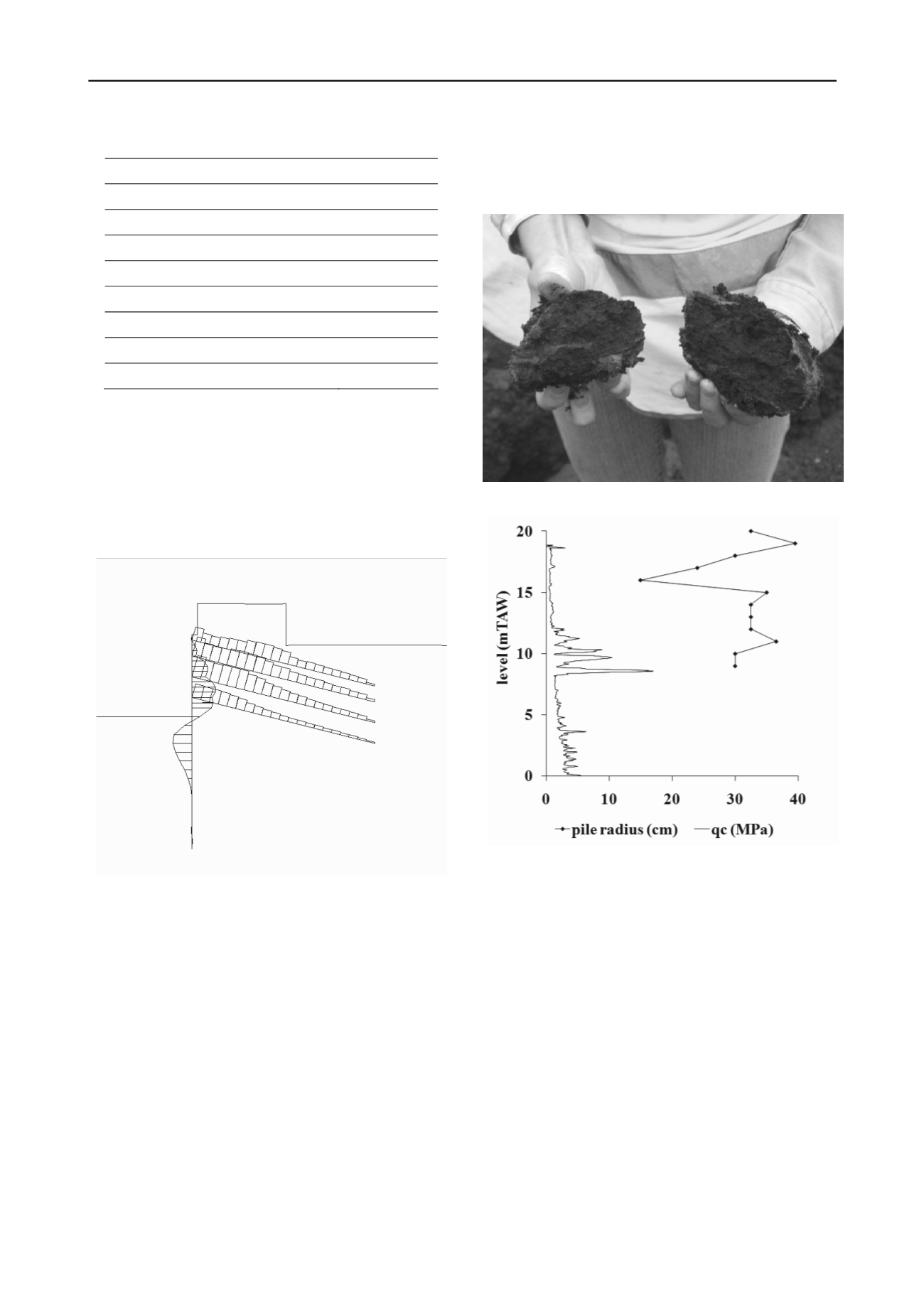
when peat is encountered. Test columns were installed prior to
the wall installation, in which diameter measurements were
carried out with a calliper in the wet column. During these tests,
chunks of more than 10 cm diameter of compacted peat were
found in the spoil (Figure 5). To aid in the realisation of the
required diameter to install the beam reinforcement, a reamer of
30 cm diameter was placed above the jet nozzles. Even with this
reamer, the minimum diameter realized was equal to that of the
reamer (Figure 6).
Figure 5. Pieces of peat found in jet grout spoil.
Figure 6. Cone resistance from CPT-E and measured diameter in wet jet
grout column.
After testing different jetting pressures, flow rates and nozzle
diameters, a suitable set of parameters was chosen. Even with
this most suitable set, it was difficult to install the last few
meters of the reinforcement, due to decantation of soil inclusion
(clay/peat) in the grout. To ease the installation, the jet grout
columns were deepened 1 m to allow for a 1 m unreinforced
length. The retaining wall was executed as primary (reinforced)
and secondary (unreinforced) columns with hart-to-hart distance
of 1 m between reinforcements. The secondary columns serve to
fill up the gap between primary columns.
Due to the nature of the fill and natural soil, a larger
diameter than conventional soil nail diameters was necessary to
provide sufficient bearing capacity of the nails. The soil nails
were also executed as jet grout nails with a diameter of 30 cm.
Pull-out tests were performed on sacrificial nails to check the
design assumptions.
Figure 7 gives a view on the retaining wall after excavation
and creation of a working platform for the new pile foundation.


