1370
Proceedings of the 18
th
International Conference on Soil Mechanics and Geotechnical Engineering, Paris 2013
The use of secant piles wall, diaphragm walls, sheet piles etc
was excluded for safety reasons, so a VHP-jet grout wall was
chosen as retaining wall.
Since both the Berliner wall and VHP-wall are closely
together and influence each other, their global design was
carried out simultaneously using the finite difference program
FLAC.
2 SITE GEOLOGY
The site is located within the alluvial basin of the river Senne,
and contains highly compressible alluvium up to a depth of 10
m. Underneath this alluvium, a gravel layer is situated with a
thickness ranging from 2 to 5 m. The deeper tertiary deposits
consist of Yperian clay, an over-consolidated clay with a
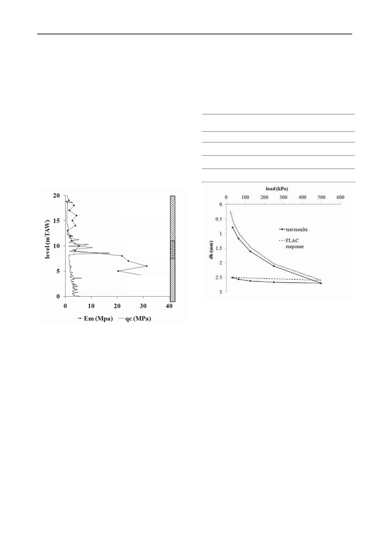
thickness of up to 16 m. Figure 2 shows the results of an
electrical CPT together with the results of a pressiometer test at
the same location. The Ménard modulus from the pressiometer
test shows the different degree of consolidation in the upper
clay layer from +8.0 to +4.0 mTAW and in the lower clay layer.
Figure 2. Cone resistance from CPT-E and Ménard modulus from
pressiometer.
3 DESIGN
3.1
Site investigation and soil parameters
Besides the extensive in situ site testing, such as cone
penetration tests (CPT’s), pressiometer tests and core drillings,
also extensive laboratory testing was carried out on undisturbed
samples. The results of these tests were used to determine the
effective strength parameters summarized in Table 1. A number
of CPT’s were performed directly from the train tracks and
through the embankment fill. The railway embankment is a
poorly compacted and silty fill.
3.2
Finite difference model
The geometry as shown in figure 1 and all of its construction
phases was modelled with the finite difference program FLAC.
Special consideration was given to the compressibility of the
alluvium. To model the stress dependant stiffness of this layer, a
“double yield” soil mechanical model was used. The double
yield model allows for plastic volumetric strain hardening,
although independent of shear strain level. Also,
unloading/reloading is taken into account with a user specified
constant ratio between loading/unloading stiffness. The model is
specifically designed for the use of isotropic compression tests,
but the results of an oedometer can be converted to fit the input
parameters. Very specific to this model is that a table of values
serves as input, and the model interpolates linearly between
these values. As a result, the (converted) oedometric test results
can serve as direct input. To check the model, a separate load
test model was used to check the input versus the modelling
results (Figure 3). Since it is very difficult to combine the
results of different oedometer tests, one representative
oedometer was chosen as single input.
Table 1. Soil parameters.
Parameter
alluvium
gravel
Yc
clay
fill
coh. (kPa)
5
0
20
4
friction (°)
22
32
25
27
E
M
(MPa)
2.5
10
27
/
p
l
(MPa)
0.5
1.9
1.6
/
Alluvial Clay
Gravel Layer
Yperian Clay
Figure 3. Comparison of model response with data from reference
oedometer test.
The jet grout wall was modelled as a continuous wall with
interface friction angle δ equal to the internal friction angle of
the surrounding soil, and with the stiffness and strength of only
the beam reinforcement of the jet grout piles. The wall is
stabilized with jet grout soil nails, which are modelled as pile
elements (with tensile and flexural strength) with an interface
cohesion (cu = qsu based on literature values).
To limit excessive swelling of the embankment, a simple
double yield model was used with constant loading and
reloading moduli.
3.3
Calculation results
The model showed that it was necessary to install the VHP
jetgrout piles till the depth of the base gravel. Otherwise,
vertical settlement of the wall would reverse wall interface
friction and would lead to excessive horizontal displacement.
Also, squeezing of the alluvium would occur when the
embedded length is further reduced.
Table 2 summarizes some results of the design calculations.
4 EXECUTION
The Berliner wall was placed with an excavator mounted
vibratory pile driver and anchored to an opposing Berliner wall
with tiebacks between the rail sleepers as shown in figure 1.


