1334
Proceedings of the 18
th
International Conference on Soil Mechanics and Geotechnical Engineering, Paris 2013
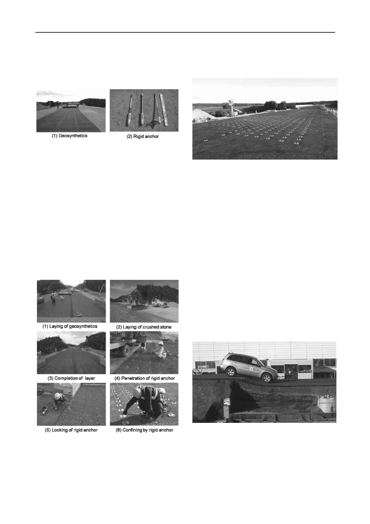
Photograph 1 (2) shows the newly developed post-tensioning
rigid steel anchor used in CRE. This anchor was improved
from a slope reinforcement anchor. The anchors is vertically
penetrated from the top to the bottom layer and locked to the
lower geosynthetics.
Photographs 1. Geosynthetics and confining rigid steel anchors using
Confined-Reinforced Earth.
3 CONSTRUCTION METHOD
Photographs 2 show the construction sequence of CRE. After
preparing the lower subgrade, the 1
st
layer of geosynthetics is
laid on the area to be reinforced (Photograph 2 (1)).
Then crushed stones are carefully laid by a bulldozer or by a
motor grader (Photograph 2 (2)) on the 1st layer of
geosynthetics and the layer of crushed stone is fully compacted
by vibrating rollers (Photograph 2 (2)). After placing three
layers of compacted crushed stone and laying of 2
nd
,3
rd
and 4
th
layers of geosynthetics (Photograph 5 (3)), rigid steel anchors
are vertically penetrated from the top to the bottom layer by the
small pile driving equipment (Photograph 2 (4)) and
mechanically locked to the lower geosynthetics employing a
small hydraulic jack ( Photograph 2 (5)).
It should be noted that the construction time of setting
anchors is very short (about 40 to 50 anchors per hour). Finally,
a top steel plate is set through a rod and is fixed to the rod
Photographs 2. Construction method of Confined-Reinforced Earth.
(Construction in Joban Highway in Fukushima, Japan, 2011)
with a nut using a torque wrench (Photograph 2 (6)). Confining
load of 30kN can be exactly maintained by setting torque. By
use of this construction method, rapid construction of CRE
becomes possible making it practical enough to apply this CRE
for road in service. Photograph 3 shows the application of CRE
for seismic retrofit of asphalt pavement on the actual highway
embankment in Joban Highway, Fukushima, Japan, constructed
in 2011.
Photograph 3. Application of Confined-Reinforced Earth for actual
highway embankment in Joban Highway, Fukushima, Japan, 2011.
4 FULL SCALE IN-SITU TEST
4.1 Trial embankment
A full-scale test of this high rigidity reinforced earth was carried
out in the field in Ibaraki, Japan, from 9
th
to 16
th
March 2011 as
shown in Photograph 4. The constructed trial embankment was
of 25m length, 4m width and 2.5m height at the top of
embankment. Full-scale asphalt pavements were placed on the
trial embankment. The asphalt concrete pavement consisted of
asphalt concrete of 50mm thickness and base course of 300mm
thickness. Two types of asphalt pavement were constructed. The
first type was conventional asphalt concrete pavement placed on
the compacted soil subgrade, while the second was asphalt
pavement placed on the high rigidity confined-reinforced earth
consisting of the crushed stone sandwiched by four layers of
geosynthetics and confined by confining rigid anchors.
We aimed at direct comparison of performance of the two
pavement types by artificially generating the differential
settlement of trial embankment such as often seen during severe
earthquakes. The forced differential settlement of the
embankment was realized by using 10 multi-controlled large
hydraulic jacks supporting the steel deck (10m long) placed
under the embankment body. The layout of the trial
embankment is shown in Figure 2.
Photograph 4. Trial embankment after testing of 550mm differential
settlement. (Confined –Reinforced Earth tested in Ibaraki, Japan,
2011)


